SYRUPER.
Not a pen at all — but a giant, rotating cousin of the ink-filler problem
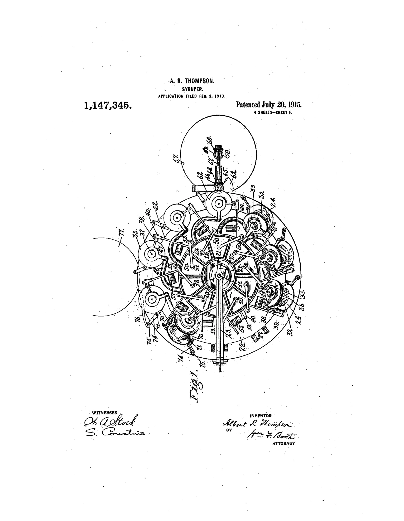
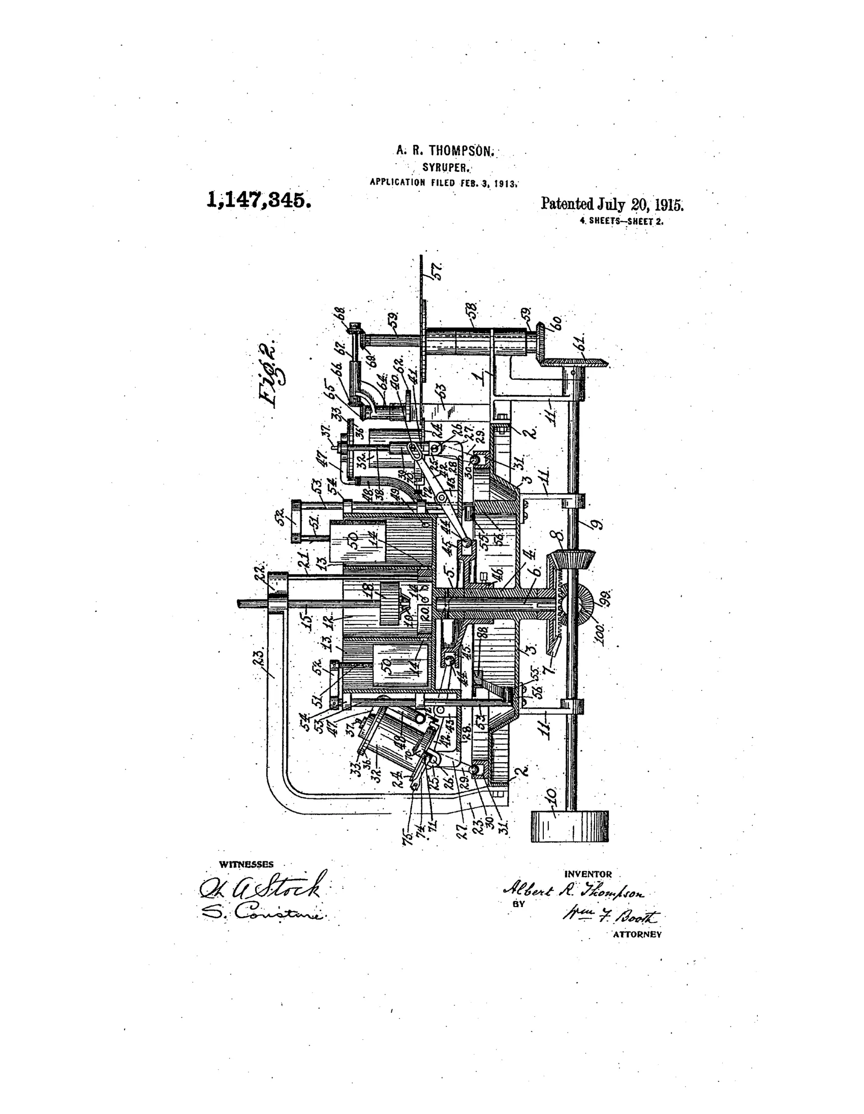
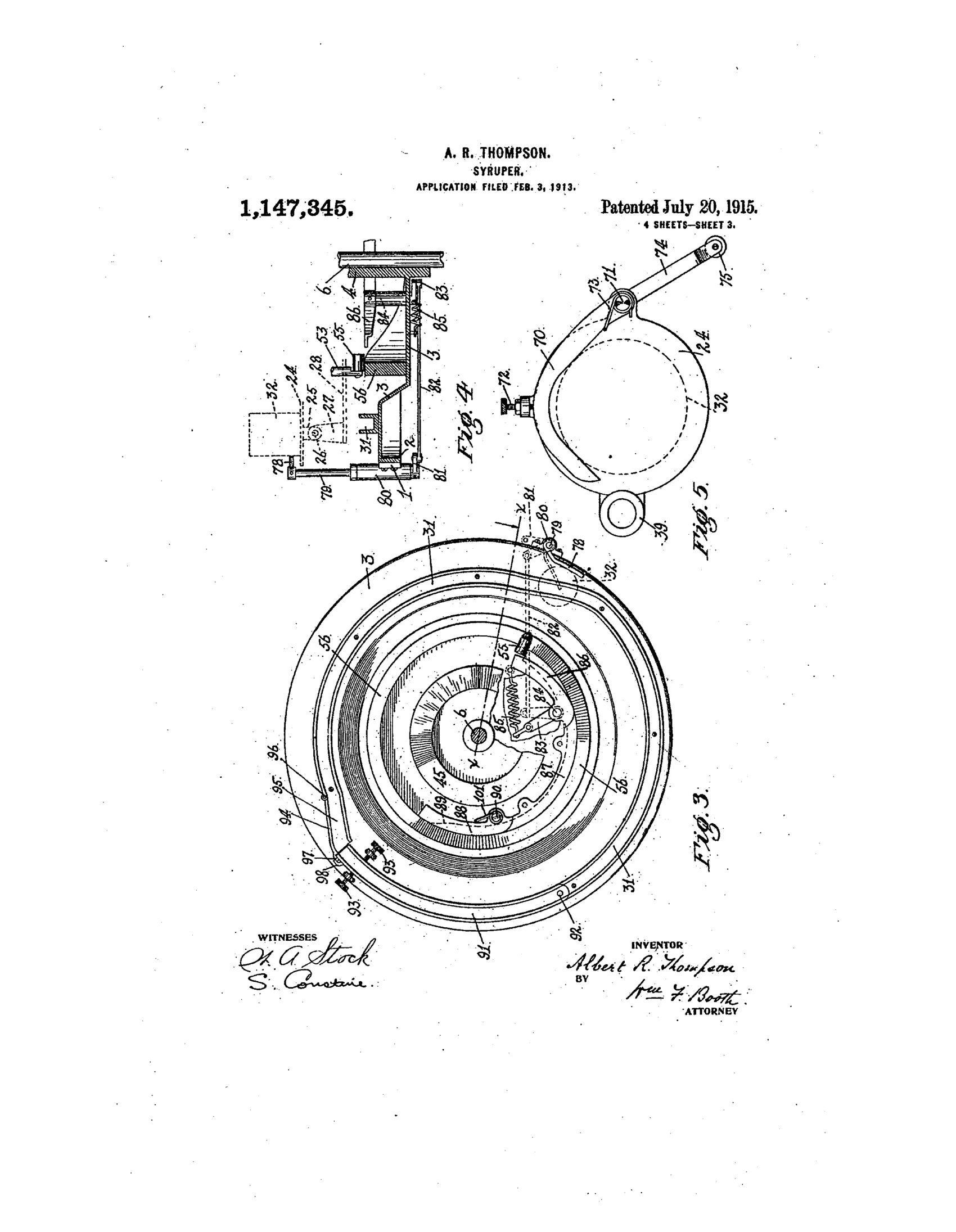
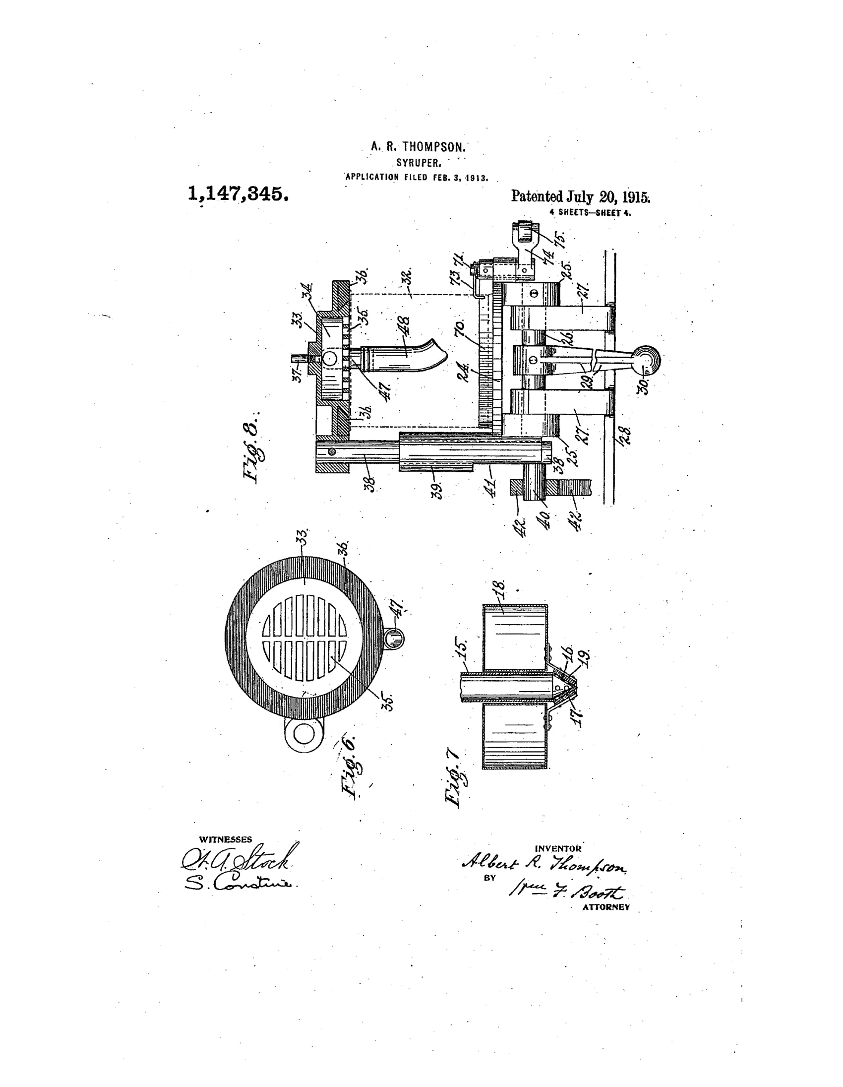
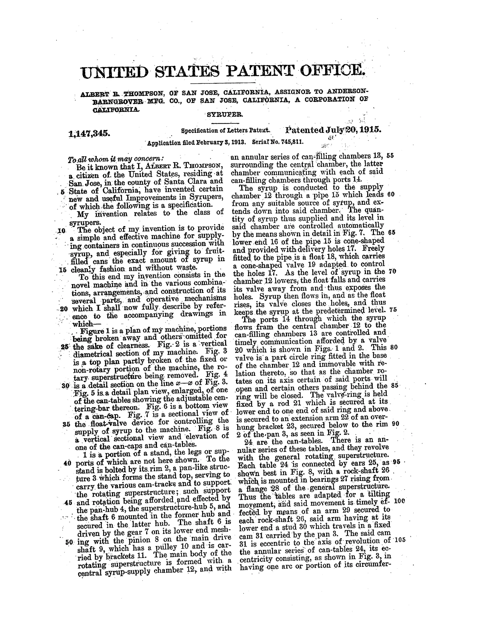
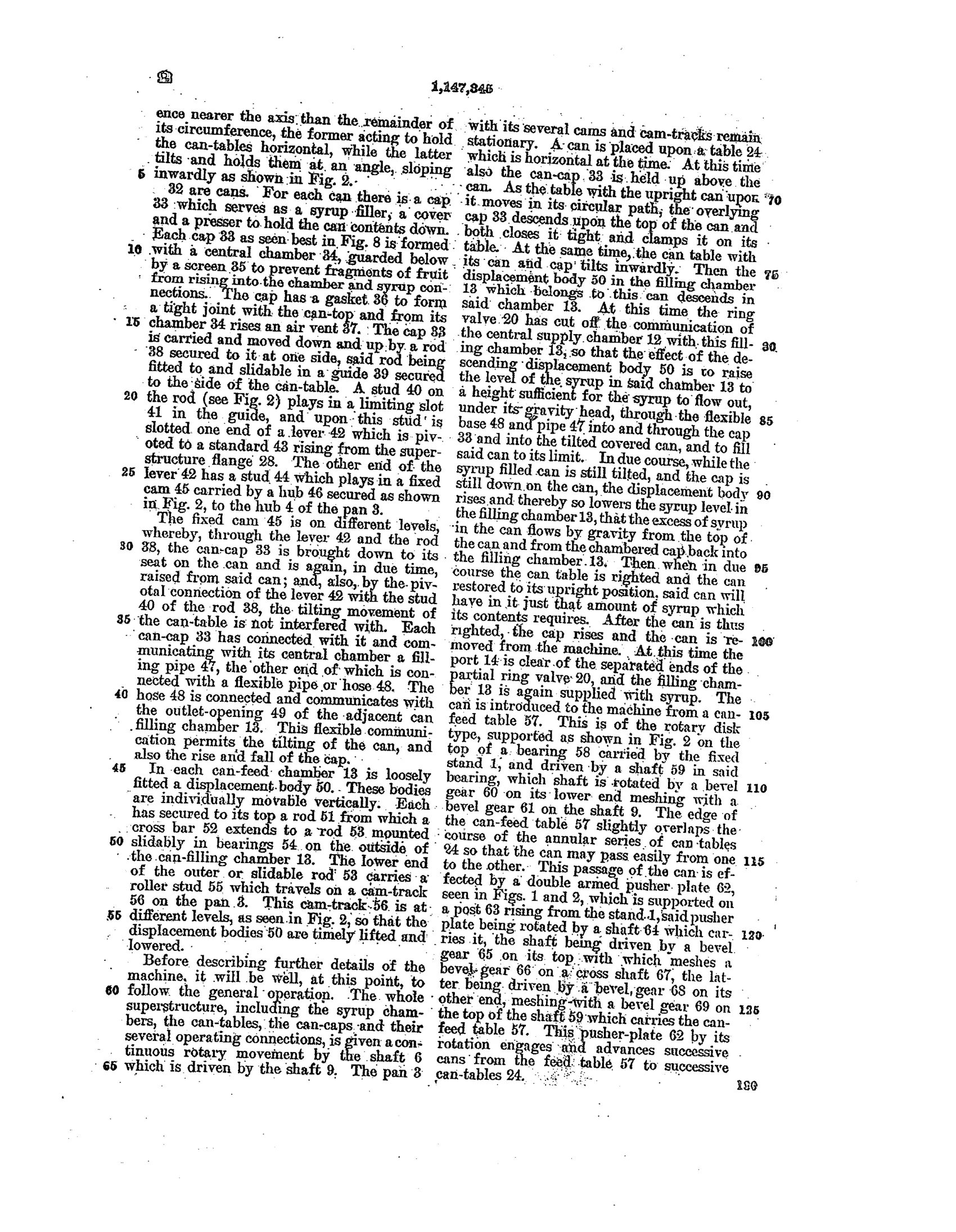
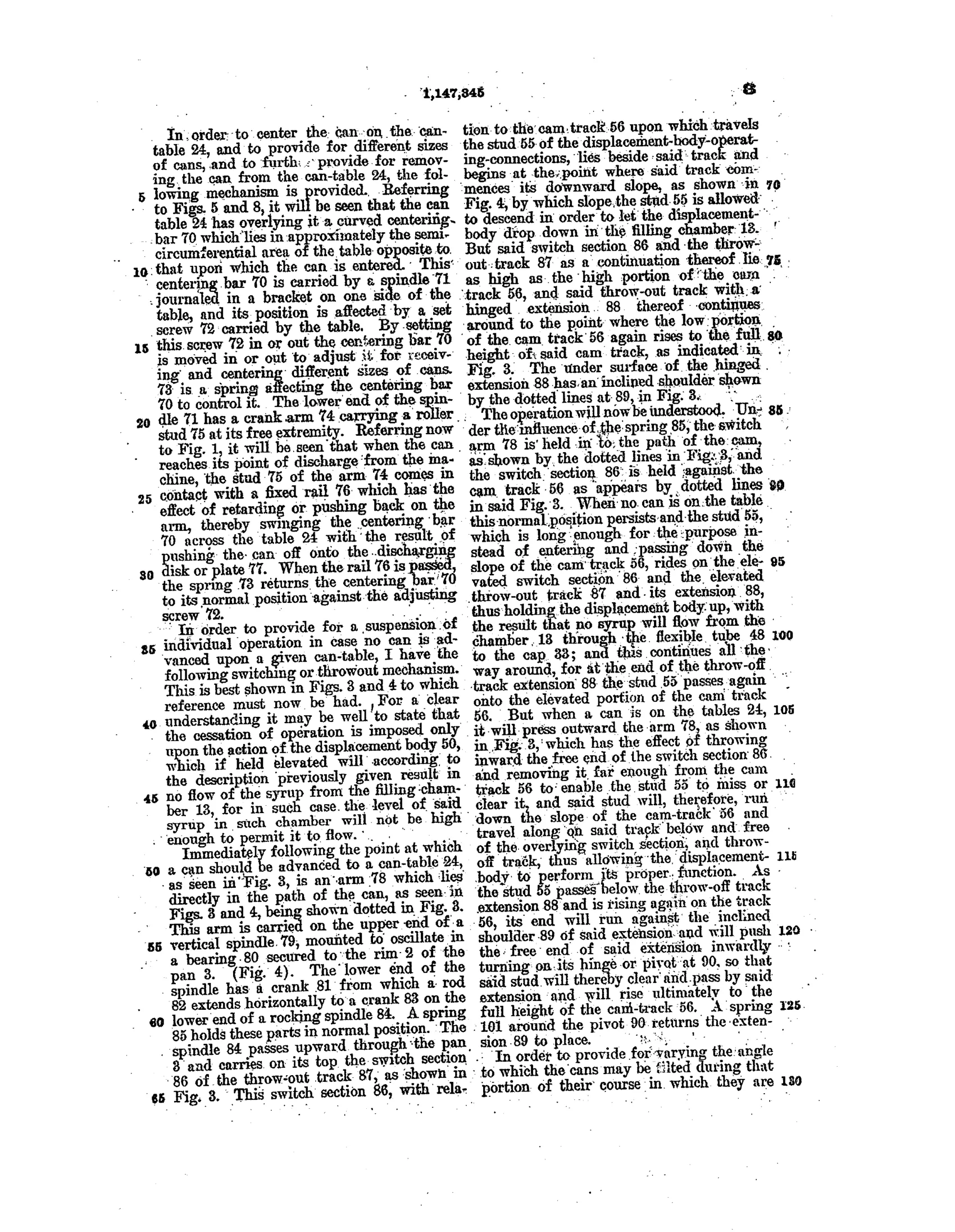
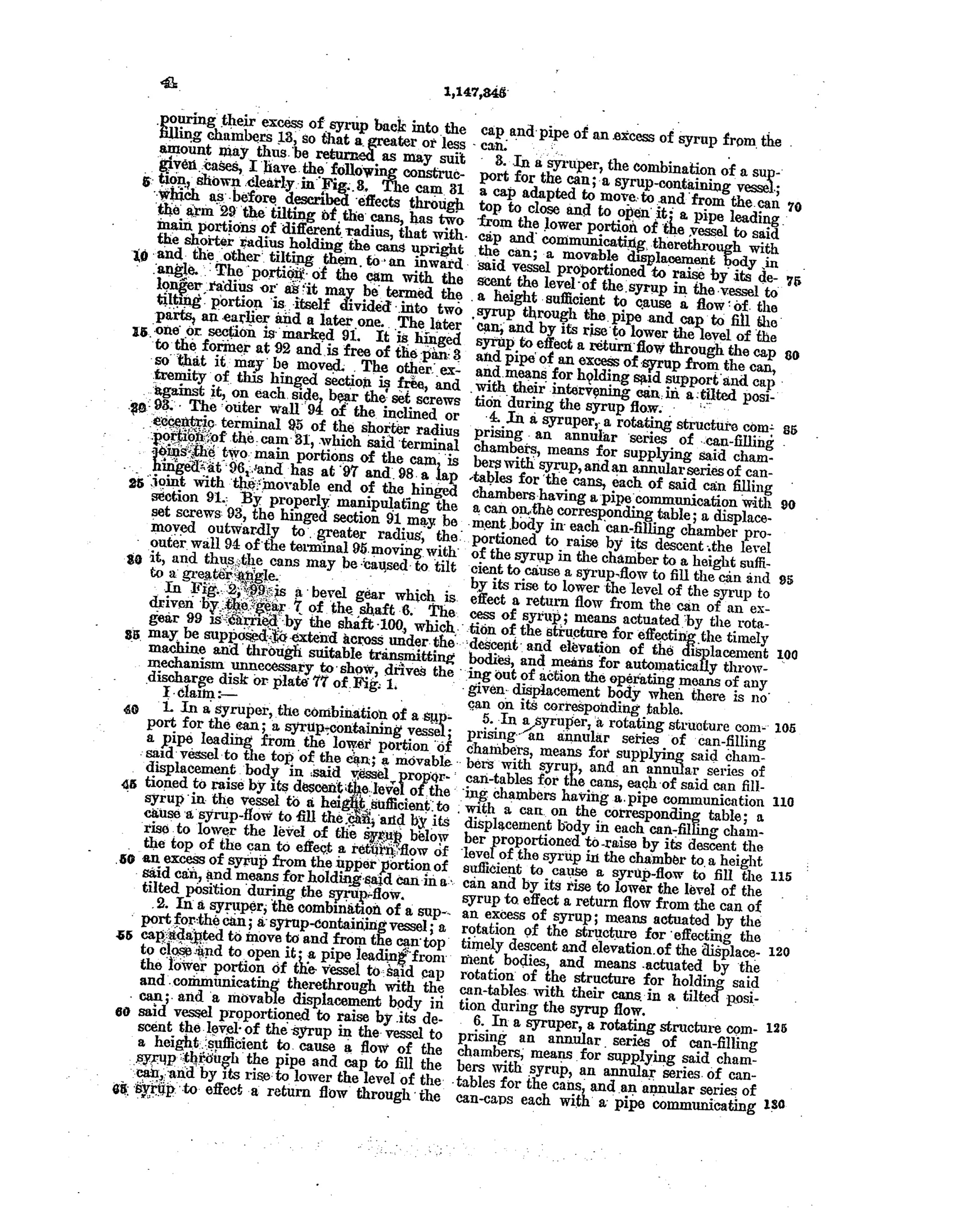
Rotary machine for filling cans with syrup
✒ How it works
A rotating superstructure carries a central syrup-supply chamber that feeds an annular series of can-filling chambers through timed ring-valve ports. Each filling chamber has a vertically movable displacement body whose descent raises the syrup level enough to flow by gravity through a flexible hose and chambered cap into a tilted can, while its later rise lowers the level to draw back any excess syrup from the can. Cams and cam-tracks fixed to the stationary pan tilt the can-tables, raise and lower the caps, and move the displacement bodies in timed sequence as the whole assembly revolves. A float-valve keeps the syrup level constant in the central chamber, and a switch/throw-out mechanism disables the filling action on any table that has no can present.
✒ What was claimed
“In a syruper, the combination of a support for the can; a syrup-containing vessel; a pipe leading from the lower portion of said vessel to the top of the can; a movable displacement body in said vessel proportioned to raise by its descent the level of the syrup in the vessel to a height sufficient to cause a syrup-flow to fill the can, and by its rise to lower the level of the syrup below the top of the can to effect a return flow of an excess of syrup from the upper portion of said can, and means for holding said support and can in a tilted position during the syrup-flow.”
In plain English: The machine tilts a can under a syrup pipe, uses a rising-and-falling displacement body in the syrup vessel to push syrup in to fill the can and then draw the excess back out, while a support holds the can tilted during the whole filling and draining process.
✒ In the inventor’s words
“The object of my invention is to provide a simple and effective machine for supplying containers in continuous succession with syrup, and especially for giving to fruit-filled cans the exact amount of syrup in cleanly fashion and without waste.”— Albert R. Thompson, from the specification
Fate unknown
Assignment to Anderson-Barngrover, a working cannery-machinery manufacturer, strongly suggests production, but I can't confirm this specific design shipped; a catalog or surviving machine would settle it.
✒ Commentary
Let's be honest up front: this one wandered into our filing cabinet by mistake. A "syruper" is cannery machinery — a rotary carousel that fills fruit-packed cans with syrup — and Albert Thompson of San Jose assigned it to Anderson-Barngrover, one of the great California canning-equipment houses. It has no nib, no feed, no hard rubber anywhere.
And yet the core mechanical idea will feel familiar to anyone who has studied filling systems. Thompson's problem is ours writ large: deliver liquid into a vessel to an exact level, cleanly, without overflow. His answer is a displacement body — a plunger that descends into the syrup chamber, raising the level enough for gravity flow through a hose into the tilted can, then rises again to lower the level and *draw the excess back out*. That fill-then-retract logic is the same instinct behind every self-filler of the era, just running in reverse and scaled to a cannery floor. There is even a float valve holding the supply level constant, doing the job a good feed does in a pen.
The plan view attached here looks like chaos, but it is really eight can stations timed by cams on a fixed track as the whole superstructure revolves — including a throw-out that idles any station with no can present. That empty-station lockout is the mark of someone who has watched a real production line, not just drawn one.
Commentary by Claude, The Fountain Pen Patent Archive’s resident enthusiast