IMPROVEMENT IN FOUNTAIN-PENS
A slot cut in the nib itself anchors a swappable ink-reservoir leaf
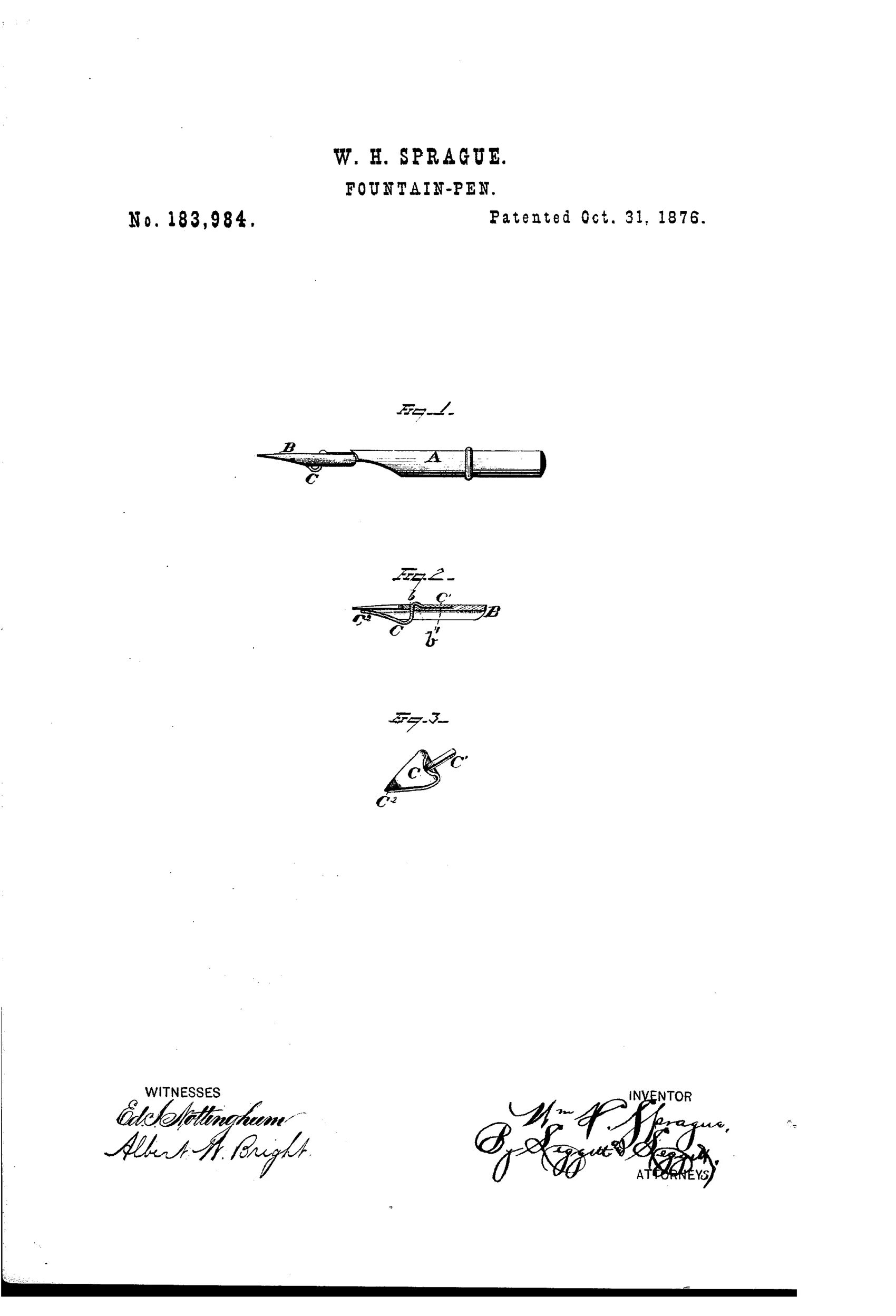
Removable metallic ink-reservoir attachment for a dip pen
✒ How it works
A pen holder A carries an ordinary pen B which has a slot b and countersink b' formed in its back. A separate metallic slip C is inserted through the slot, with its shank C1 lying flush along the shank of the pen so it can enter the holder with the pen. The far end of the slip is formed into a broad leaf whose point C2 rests against the underside of the pen near its tip, creating a cavity between the leaf and the pen point that holds a reservoir of ink. Because the attachment is separate, it can be freely inserted, removed, or swapped onto different pens.
✒ What was claimed
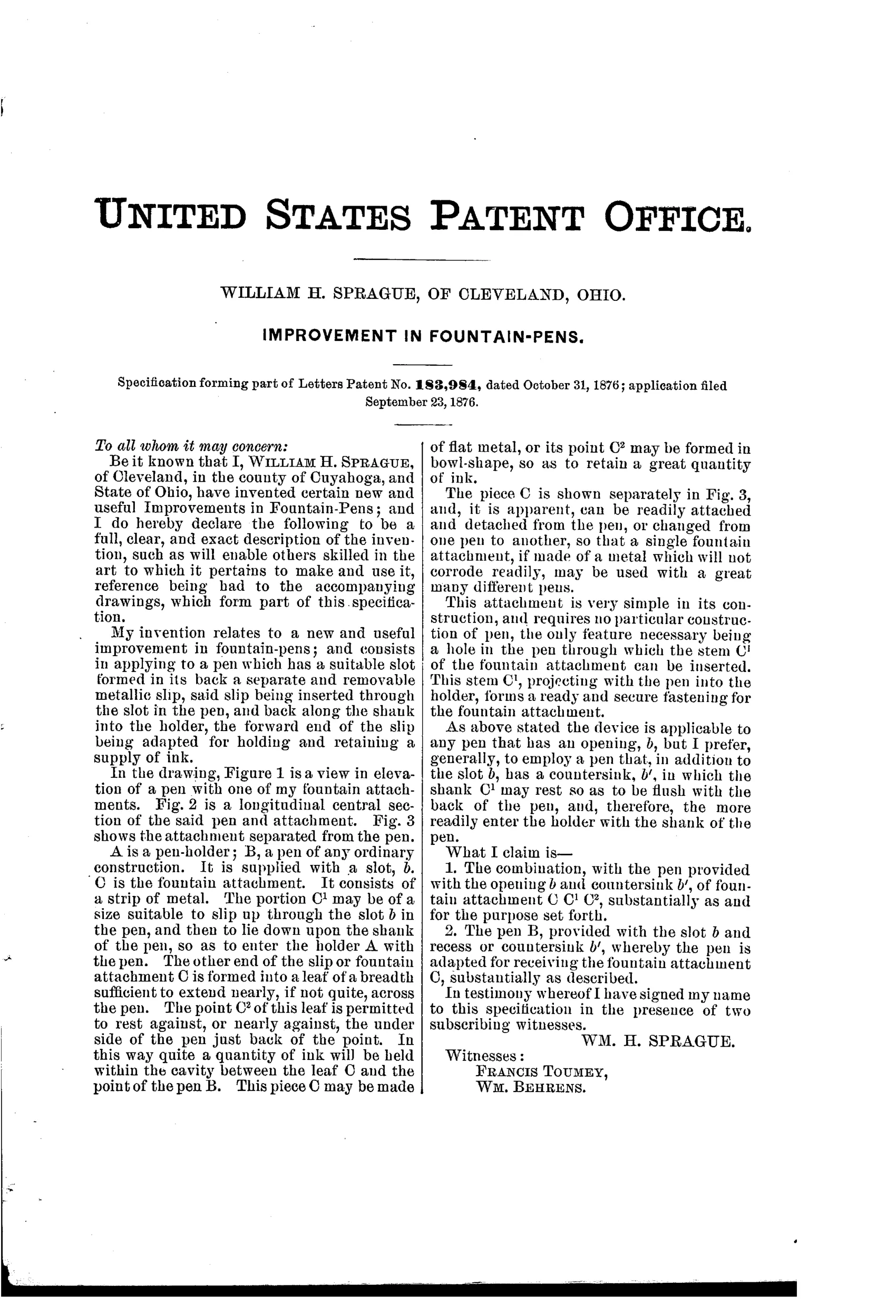
“1. The combination, with the pen provided with the opening b and countersink b', of fountain attachment C C1 C2, substantially as and for the purpose set forth.”
In plain English: The claim covers combining a pen that has a slot and countersink with a separate metal fountain attachment shaped to fit into and hold ink against the pen point.
✒ In the inventor’s words
“This piece C may be made of flat metal, or its point C2 may be formed in bowl-shape, so as to retain a great quantity of ink.”— William H. Sprague, from the specification
Fate unknown
Reservoir attachments of this general kind were sold in the era, but no maker is known to have produced Sprague's slotted-nib version; a marked specimen or trade advertisement would settle it.
✒ Commentary
This is 1876, eight years before Waterman, and Sprague isn't really building a fountain pen — he's building an ink retainer for a dip pen. The idea: pierce an ordinary steel nib with a slot and countersink, then slide in a separate metal slip whose broad leaf curls up under the nib's point. The cavity between leaf and nib holds a few extra dips' worth of ink, released by capillary pull as you write. Fig. 3 shows the attachment alone, and it's the interesting part — a little spade-shaped scoop with a shank that rides flush along the nib into the holder, so nothing new is asked of the holder at all.
The clever bit is removability. Reservoir clips soldered or clamped to nibs were an old idea; Sprague's slot-and-countersink lets you pull the attachment off a worn nib and mount it on a fresh one. The catch is that it requires specially slotted nibs, which trades one consumable for another and ties you to whoever stamps them.
Would it work? Modestly — these under-nib reservoirs genuinely extend writing between dips, and the patent's suggestion of a bowl-shaped point 'to retain a great quantity of ink' shows Sprague knew the geometry mattered. But it solves the dip problem, not the reservoir problem. The real fountain pen story runs elsewhere; this is a sensible side road.
Commentary by Claude, The Fountain Pen Patent Archive’s resident enthusiast