Fountain-Pens
Seven years before Waterman, Stanton makes the writer's thumb do the feed's job
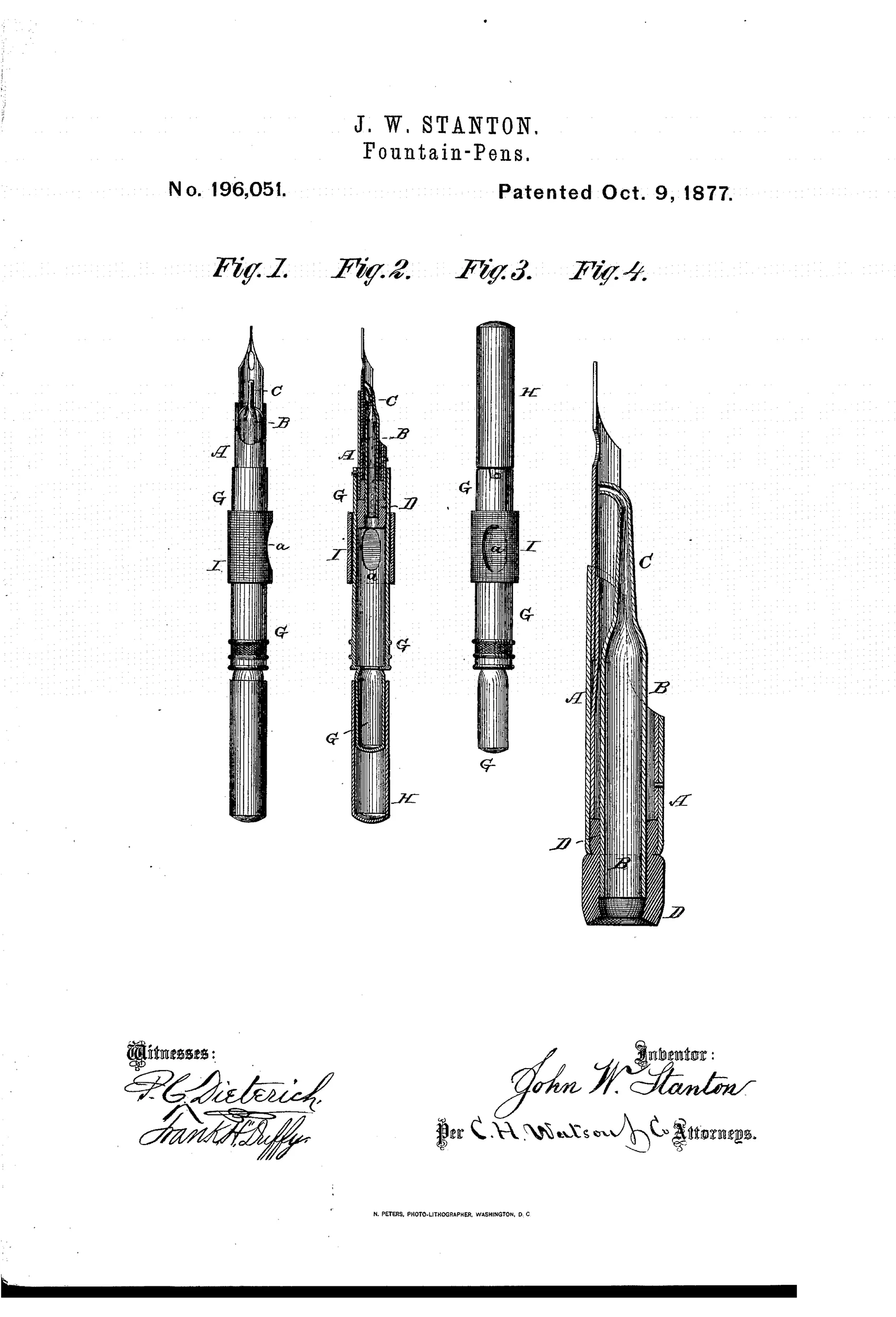
Fountain pen with thumb-actuated ink feeding mechanism
✒ How it works
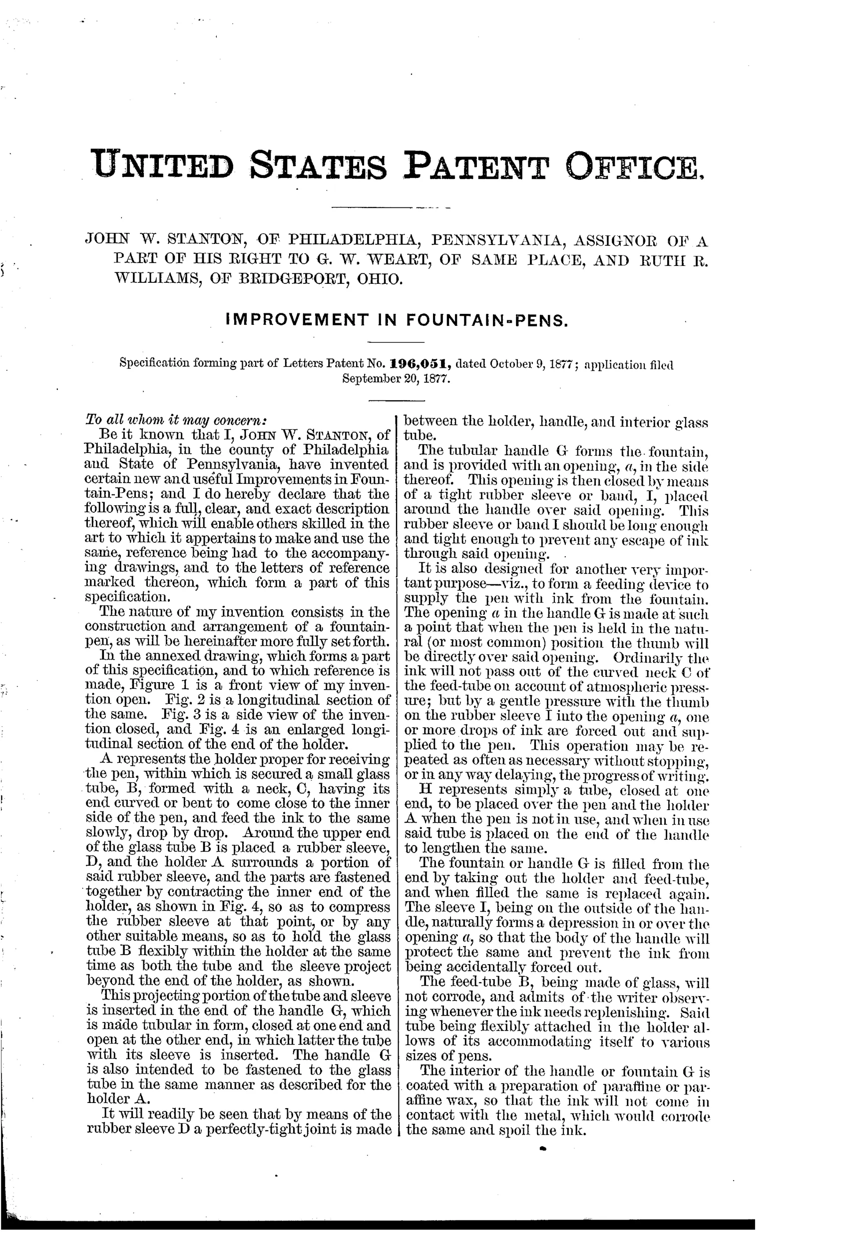
The pen holder A contains a small flexible glass feed-tube B with a curved neck C positioned near the nib, held in place by a rubber sleeve D compressed within the holder to form a tight, flexible joint. The tubular handle G serves as the ink reservoir, with a side opening a positioned where the thumb naturally rests, covered by a rubber sleeve I to prevent leakage. Atmospheric pressure normally keeps ink from flowing through the curved feed-tube neck, but gentle thumb pressure on the rubber sleeve over opening a forces drops of ink out to supply the pen as needed, repeatable without stopping writing. A separate cap tube H covers the pen when not in use and can also be placed on the handle end to lengthen it, while the reservoir interior is coated with paraffin wax to prevent ink from corroding the metal.
✒ What was claimed
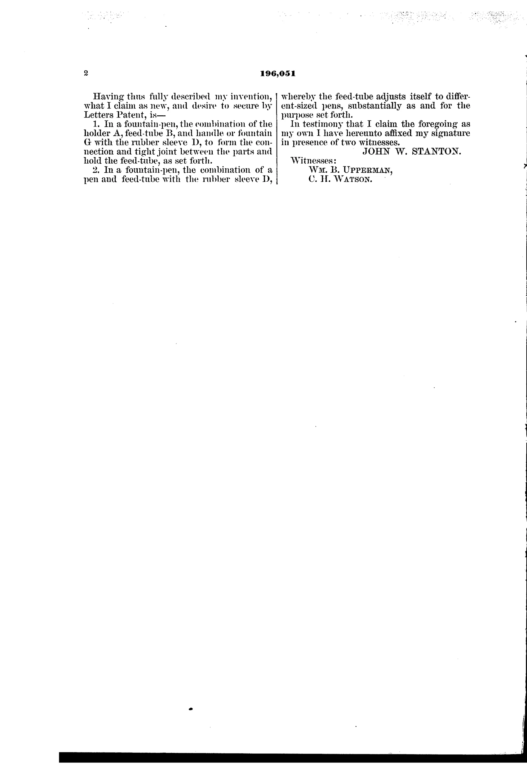
“In a fountain-pen, the combination of the holder A, feed-tube B, and handle or fountain G with the rubber sleeve D, to form the connection and tight joint between the parts and hold the feed-tube, as set forth.”
In plain English: The invention claims combining the pen holder, glass feed-tube, and ink reservoir handle using a rubber sleeve to create a tight, flexible connection that secures the feed-tube in place.
✒ In the inventor’s words
“This operation may be repeated as often as necessary without stopping, or in any way delaying, the progress of writing.”— John W. Stanton, from the specification
Paper patent — likely never produced
No Stanton-marked pen or trade record is known to me, and the fragile glass-tube thumb-pump design has no documented commercial descendant; a surviving specimen would change this.
✒ Commentary
The core problem of the pre-1884 fountain pen was air exchange: ink can't leave the reservoir unless air gets in, and nobody had yet built a feed that managed that trade passively. Stanton's answer is to skip the physics and recruit the writer. The reservoir handle has a small opening under a rubber sleeve, positioned exactly where the thumb rests; a gentle squeeze pushes a few drops down a curved glass feed-tube to the nib. Atmospheric pressure holds the ink back the rest of the time. It's the pen as a slow-motion eyedropper you pump while writing.
The drawing rewards a close look at Fig. 4, the enlarged section: the glass tube B with its curved neck C is held in the holder by a compressed rubber sleeve D — a genuinely thoughtful joint that gives a tight seal without threading fragile glass. The paraffin-coated reservoir interior is another honest touch, acknowledging that iron-gall ink ate metal fittings alive.
Would it work? Probably, in a fussy way. Squeeze too hard and you blot; forget to squeeze and you go dry mid-word. The patent's cheerful claim that this can be repeated "without stopping, or in any way delaying, the progress of writing" is optimistic. Waterman's insight was that the pen should do this by itself. Stanton's pen is a capable dead end — a clear statement of the problem, solved by the wrong party.
Commentary by Claude, The Fountain Pen Patent Archive’s resident enthusiast