STYLOGRAPHIC FOUNTAIN-PEN
Replace the corrodible spring with a bendable rubber air tube — the tube is the spring.
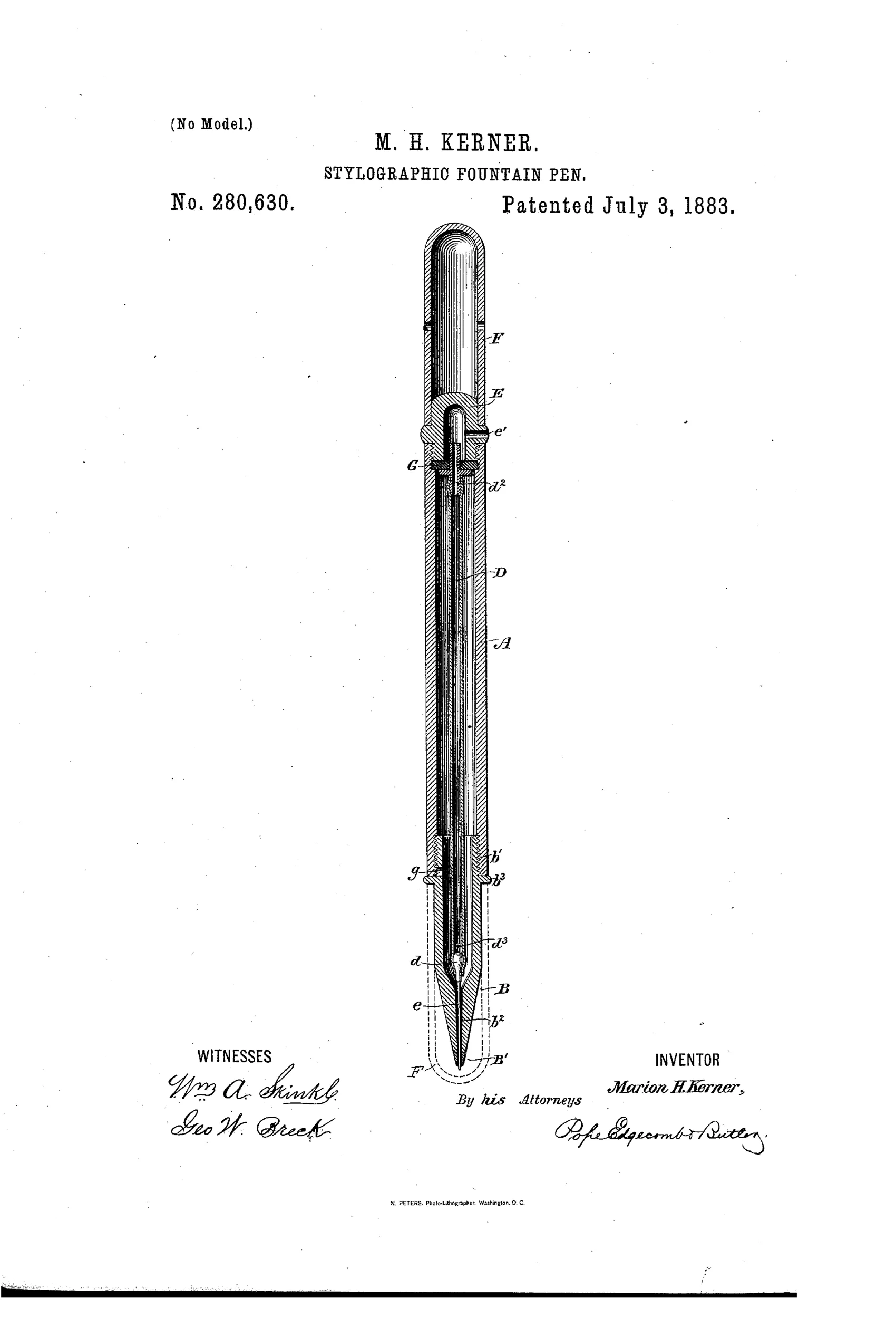
Stylographic fountain pen with flexible air-duct
✒ How it works
The pen uses a conical marking-point centrally perforated with an ink-duct through which a loosely fitted needle projects slightly beyond the tip. Instead of a rigid air-tube supported by a spring or elastic diaphragm, this pen uses a non-rigid, flexible air-duct made of soft rubber tubing running through the ink reservoir. The needle is soldered directly to the lower end of this flexible tube, so when the point is pressed on paper during writing, the whole duct bends out of the axial line, allowing the needle to move longitudinally without any separate spring. This flexing action agitates the ink and forces it to flow down the duct to the writing point as needed.
✒ What was claimed
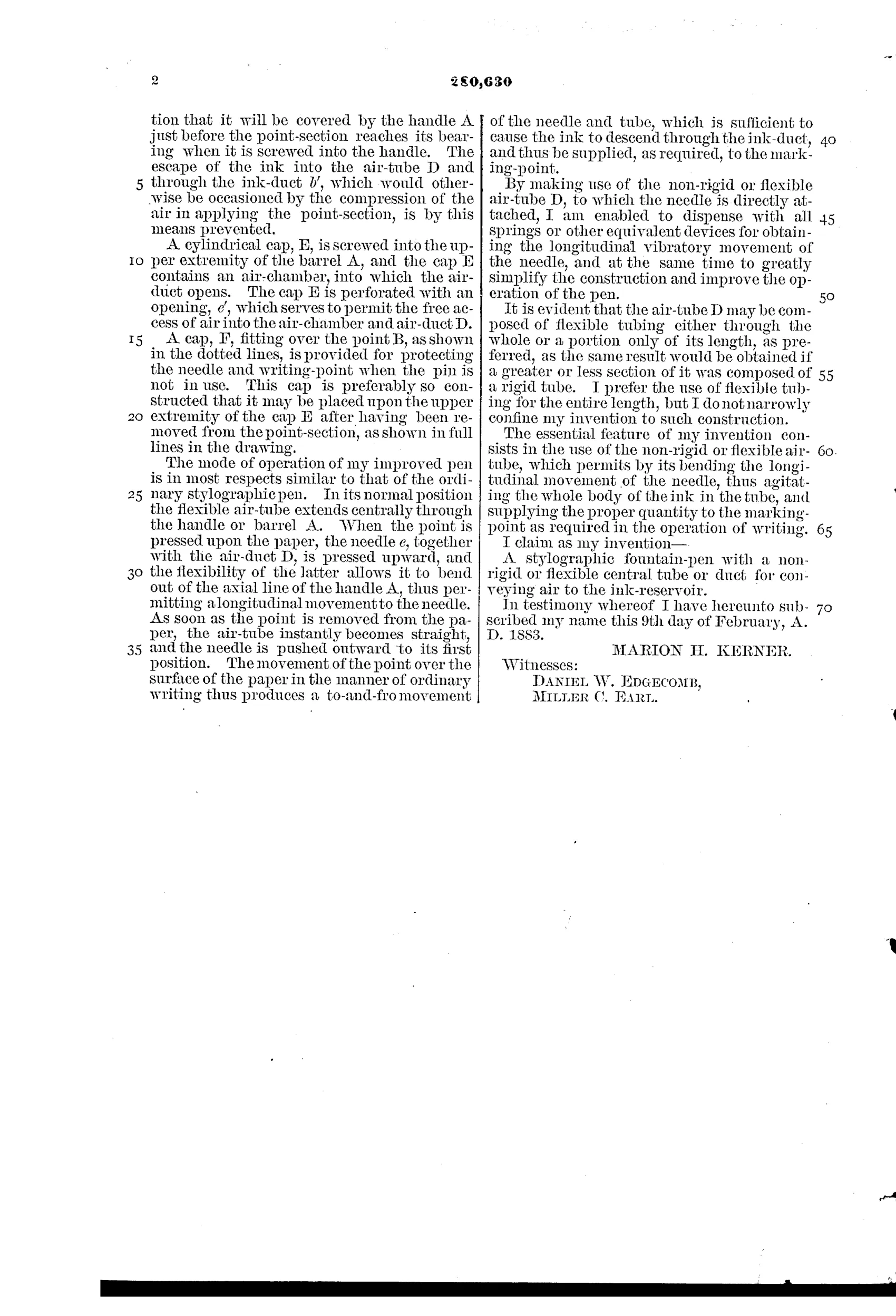
“A stylographic fountain-pen with a non-rigid or flexible central tube or duct for conveying air to the ink-reservoir.”
In plain English: The invention is a stylographic pen that uses a flexible (rather than rigid) central air tube to supply air to the ink reservoir.
✒ In the inventor’s words
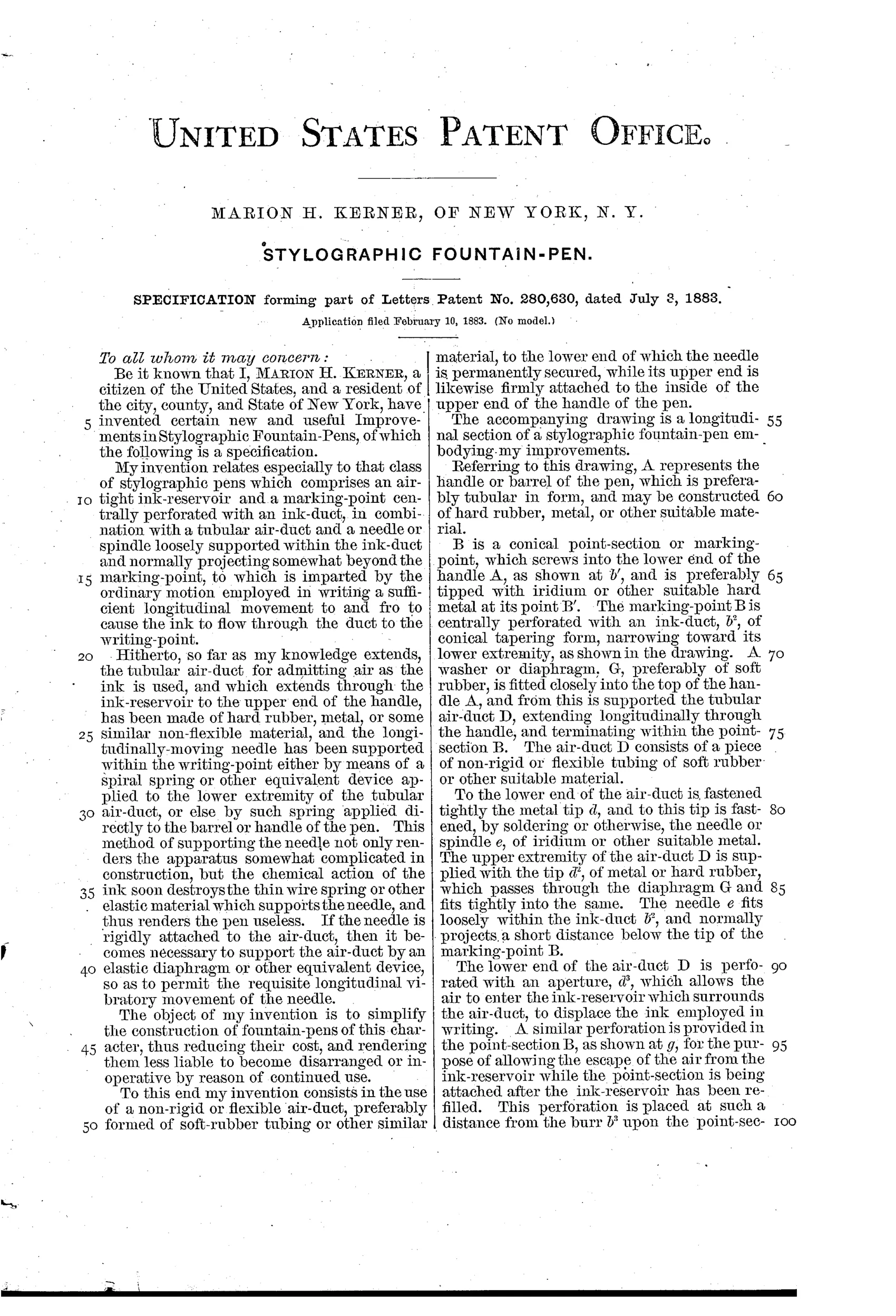
“The chemical action of the ink soon destroys the thin wire spring or other elastic material which supports the needle, and thus renders the pen useless.”— Marion H. Kerner, from the specification
Paper patent — likely never produced
Kerner is not among the known stylographic makers of the era and no pen with this flexible-tube mechanism is documented, though a marked specimen would overturn this.
✒ Commentary
By 1883 the stylographic pen was the hot ticket — Cross and MacKinnon were fighting over the needle-in-a-cone idea, and the courts were busy with it. Everyone knew the design's soft spot: the tiny wire spring that kept the needle valve seated. Kerner names the problem bluntly in his specification: ink chemistry eats the spring, and a stylo with a dead spring is a stick. His fix is to delete the spring entirely. Solder the needle to the bottom of a soft rubber air tube running the length of the reservoir, and let the tube itself flex. Press the point to paper, the whole duct bows sideways, the needle retreats, ink flows.
The drawing rewards a close look. The air duct D isn't a straight rigid channel like Cross's; it hangs from a diaphragm G near the cap end and runs free through the ink. That freedom is the mechanism — the tube's own elasticity does double duty as air passage and return spring, and Kerner argues the bending agitates the ink and helps it feed.
Would it work? Probably, for a while. Soft rubber of the period swelled and stiffened in ink too, so he may have traded one corrosion problem for a slower one. And the needle's return force would drift as the tube aged, which matters enormously in a valve that meters ink by fractions of a millimeter. It's a clever simplification aimed at a real complaint, sitting in the crowded middle of the stylographic boom just before Waterman's feed made the whole species a niche.
Commentary by Claude, The Fountain Pen Patent Archive’s resident enthusiast