SELF-FEEDING DRAWING-PEN
A ruling pen that feeds itself — through a tube running outside the blades
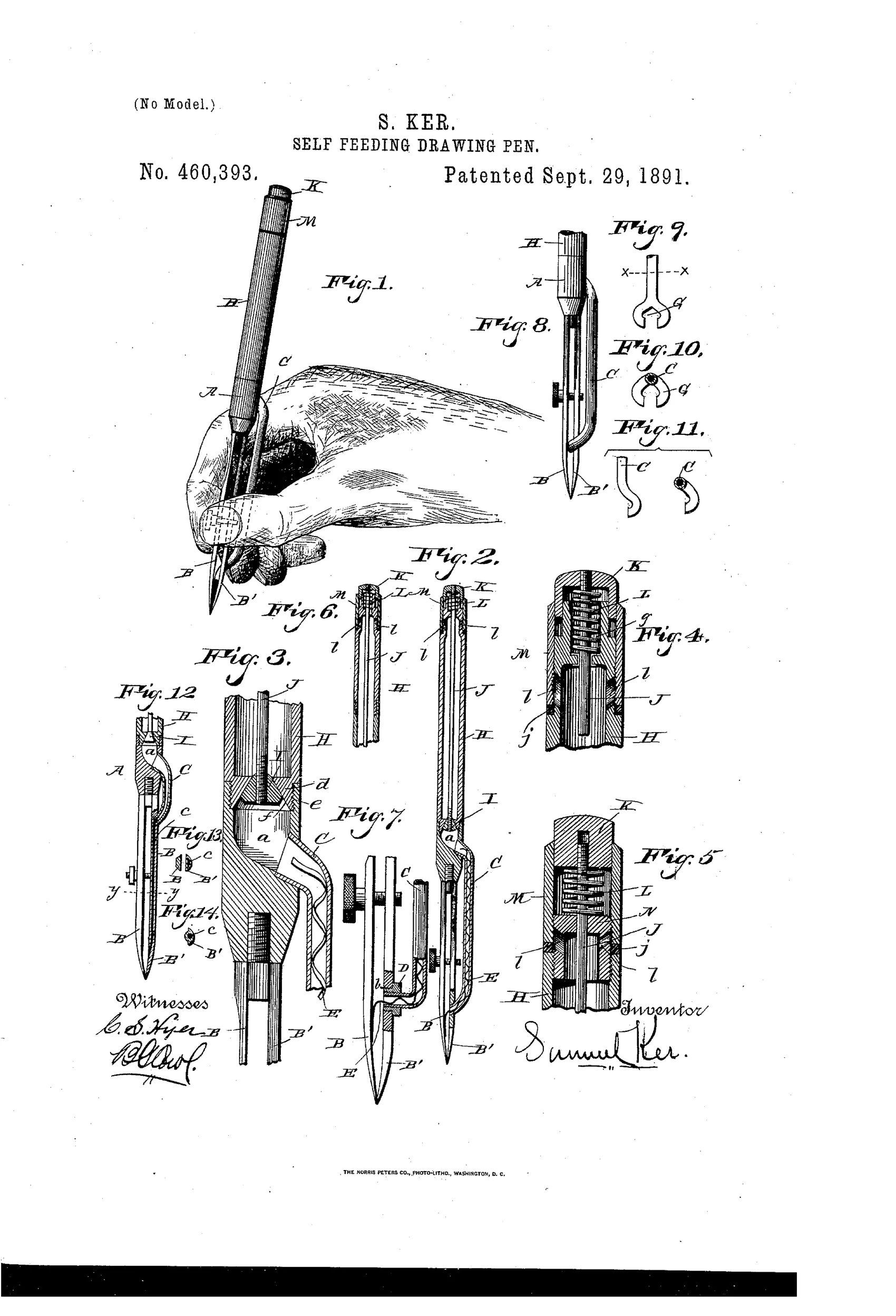
Self-feeding drawing pen with exterior ink conduit
✒ How it works
A chambered head carries the pen-points, and a conduit outside the head and blades delivers ink from a reservoir near the point. A spring-actuated valve in the reservoir controls the flow of ink into the chambered head, while a corrugated feeder-spring within the conduit regulates and prevents clogging of the ink feed. The conduit's discharge end may be rigid, flexible, or semi-flexible, and is detachably connected to the pen-leg so that adjusting the blades together (for a fine line) compresses a flexible tip to reduce ink flow, while relaxing them expands the tip for a heavier line.
✒ What was claimed
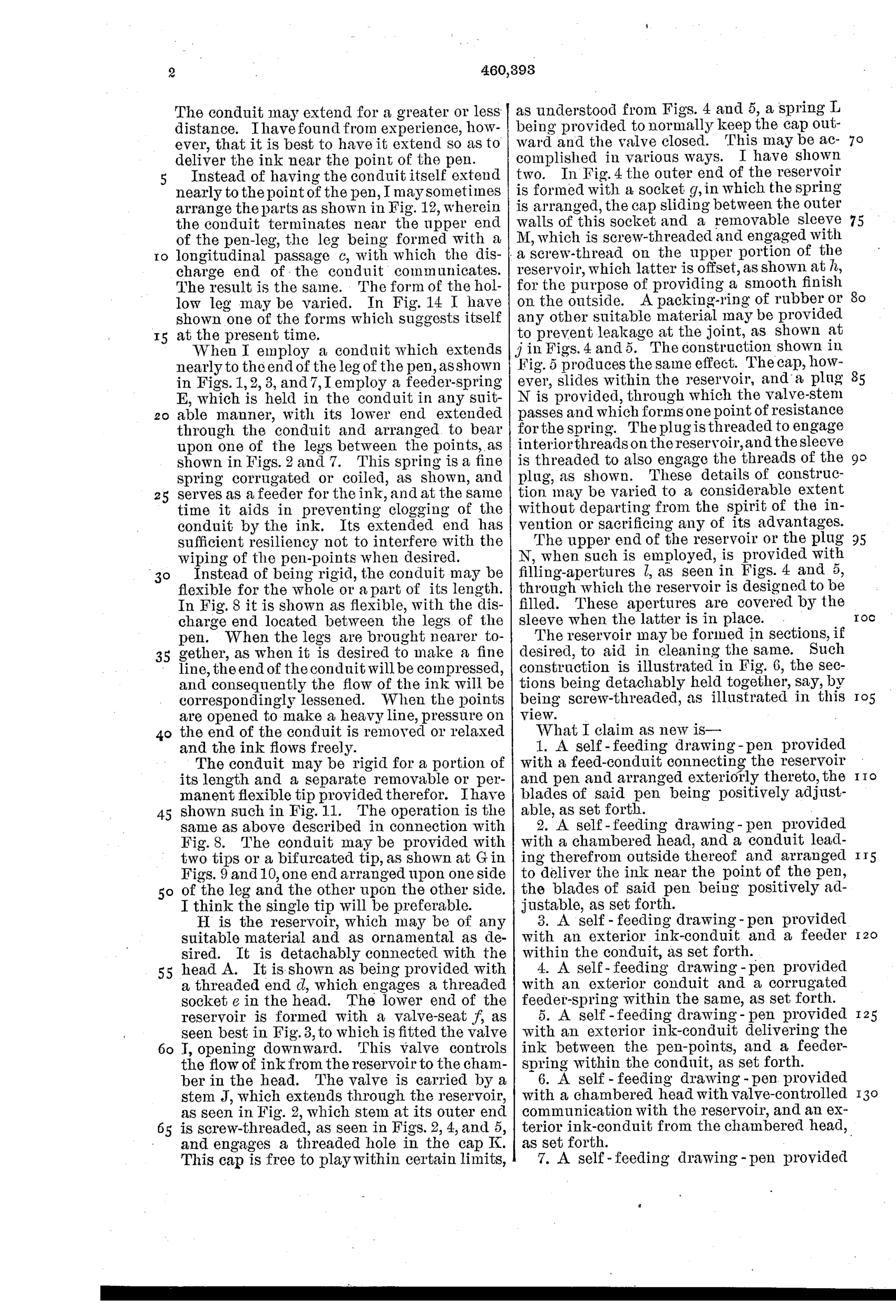
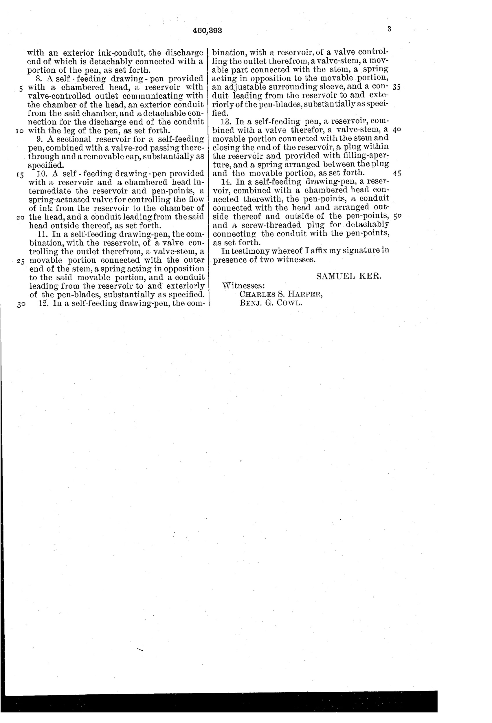
“1. A self-feeding drawing-pen provided with a feed-conduit connecting the reservoir and pen and arranged exteriorly thereto, the blades of said pen being positively adjustable, as set forth.”
In plain English: A drawing pen with an ink tube running outside the pen body connecting the reservoir to the point, with adjustable blades.
✒ In the inventor’s words
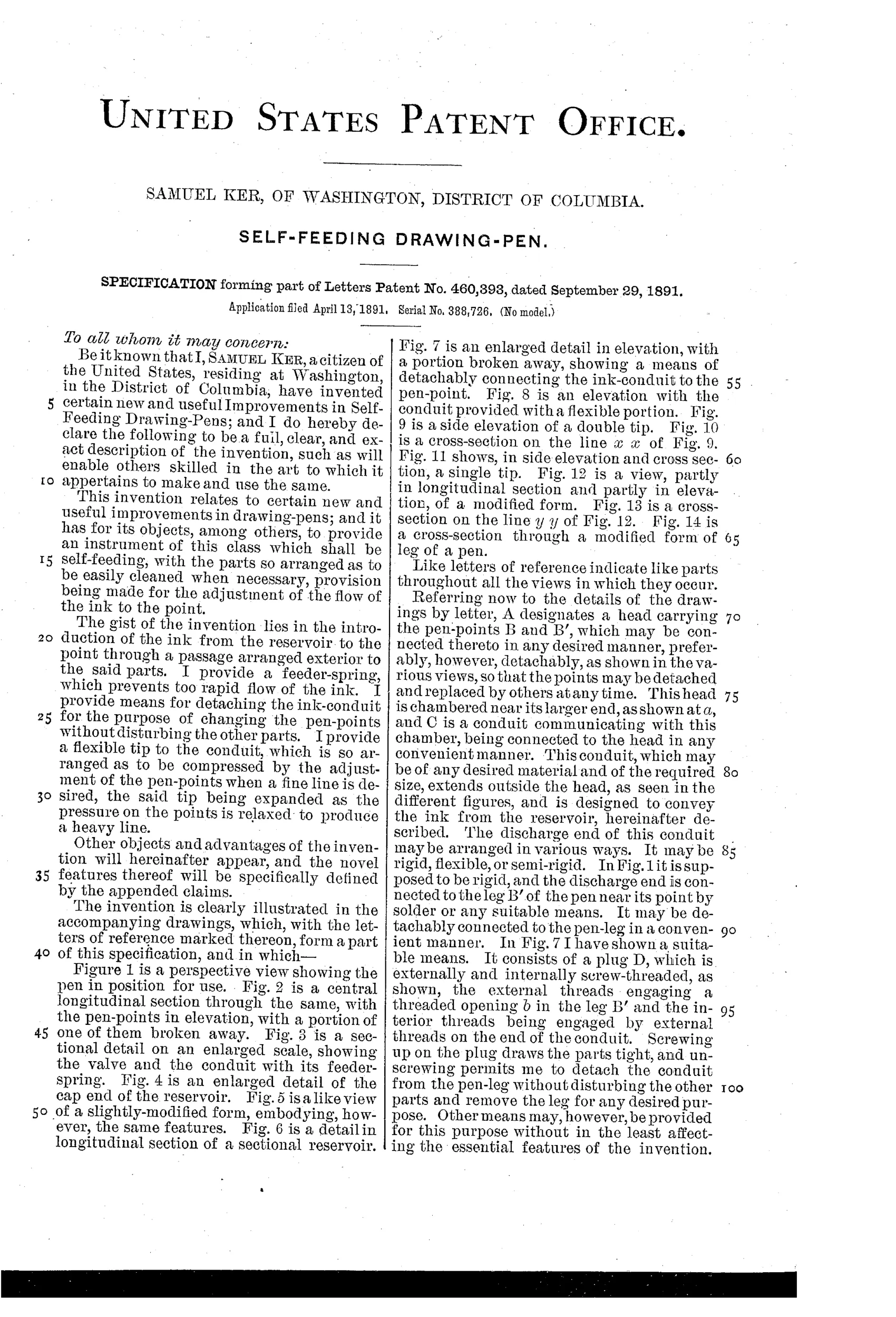
“The gist of the invention lies in the introduction of the ink from the reservoir to the point through a passage arranged exterior to the said parts.”— Samuel Ker, from the specification
Fate unknown
No maker or surviving specimen is known to me; a marked example or trade-catalog listing would settle it.
✒ Commentary
This isn't a fountain pen for writing letters; it's a ruling pen — the two-bladed drafting instrument that draftsmen dipped every few inches while inking a drawing. Ker's target problem is real and irritating: constant re-dipping breaks the rhythm and risks blots on a finished sheet. His answer is a reservoir in the handle, a spring-actuated valve to meter the flow, and — the part he flags himself as "the gist" — an ink conduit routed outside the head and blades rather than through them.
That exterior routing is smarter than it looks. Ruling pen blades must stay adjustable (the thumbscrew sets line width), so boring a feed channel through them would fight the adjustment. Ker instead has the conduit's flexible tip compress as the blades close for a fine line, throttling the ink, and expand as they open for a heavier one — the width adjustment and the flow regulation ride on the same motion. Fig. 7 shows the detachable connection, and the corrugated feeder-spring in Fig. 3 is a period-typical anti-clogging trick, cousin to the wire feeds in contemporaneous fountain pens.
The weakness is the same one that dogged every self-feeding ruling pen: drawing inks are heavy with pigment and dry fast, and that narrow exterior tube is a clog waiting to happen. Draftsmen kept dipping for another half-century, which tells you how these schemes fared. Still, it's a thoughtful piece of 1891 engineering on a problem the fountain-pen mainstream ignored.
Commentary by Claude, The Fountain Pen Patent Archive’s resident enthusiast