COMBINED INK-WELL AND PENHOLDER.
A dip pen on an umbilical cord: gravity-fed ink through a rubber tube
Combined inkwell and penholder with tube feed
✒ How it works
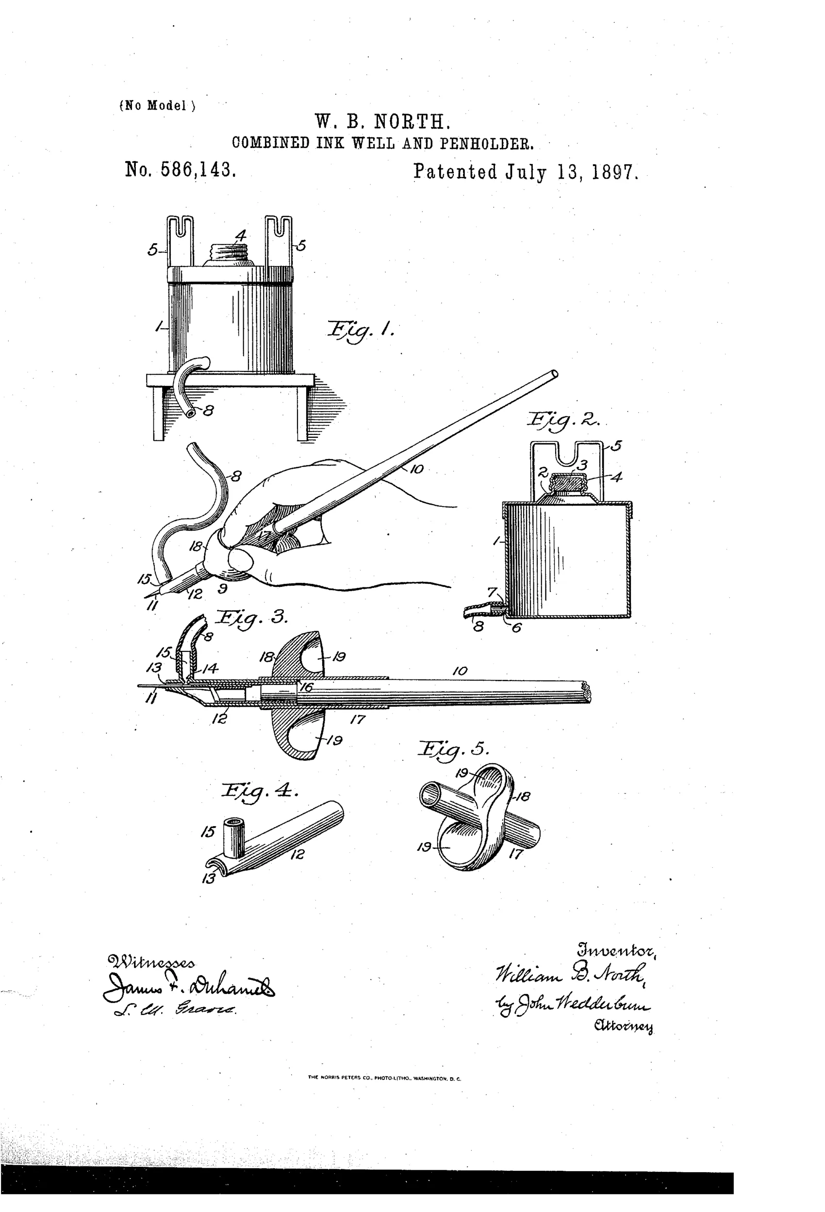
An ink-well with a filling opening and cap sits on a shelf above a penholder that rests on brackets when not in use. A flexible rubber tube connects a nipple on the bottom of the ink-well to a tubular cap on the penholder's handle, delivering ink by gravity to the pen-point. A sliding sleeve with finger-shaped guide recesses is mounted on the handle to position the user's fingers correctly and to keep ink off the fingers. When the pen is returned to the rack above the ink level, the flow of ink automatically stops.
✒ What was claimed
“In a device of the character set forth, the combination of an ink-well, a solid penholder separate from and adapted to be moved independently of said ink-well, and a flexible tube connecting said ink-well and said penholder, whereby a constant supply of ink is furnished to said penholder while the same is in its operative position.”
In plain English: The invention combines an ink-well with a separate penholder connected by a flexible tube, so the pen gets a steady ink supply while in use.
✒ In the inventor’s words
“The ink from the said well will flow through the flexible rubber tube 8 and supply ink as it is needed to the pen-point 11 through the tubular cap 12 on the outer end of the handle 10.”— William B. North, from the specification
Fate unknown
No maker or surviving example is documented for this tethered design; a marked specimen or catalog listing would settle it.
✒ Commentary
While Waterman and his rivals were fighting over capillary feeds — how to get air into a sealed barrel as ink comes out — William B. North of Sikeston, Missouri sidestepped the whole problem. Don't put the reservoir in the pen at all. Leave the inkwell on its shelf, run a flexible rubber tube down to a hollow penholder, and let gravity do the feeding. The pen never runs dry and never needs dipping, so long as you don't mind writing while tethered to your desk.
The hydraulics are the honest part. Flow control depends entirely on relative height: hang the holder back on its bracket above the ink level and the siphon stops. That's real physics, and it works — right up until someone drops the pen off the edge of the desk, at which point the same siphon happily empties the well onto the floor. There's no valve anywhere in the drawing.
The detail a casual reader skips is Fig. 5, the sliding sleeve with molded finger recesses. North knew his gravity feed would weep ink up the handle, so he built a finger guard and called it an ergonomic grip. That's an inventor quietly patching his own leak. As a category entry it's a dead end — the self-contained fountain pen made tethered pens pointless — but it's a charming reminder that in 1897 the feed problem was hard enough that a rubber hose looked like a fair trade.
Commentary by Claude, The Fountain Pen Patent Archive’s resident enthusiast