IMPROVEMENT IN PENS
A hinged trapdoor reservoir that swings open for cleaning, fourteen years before Waterman
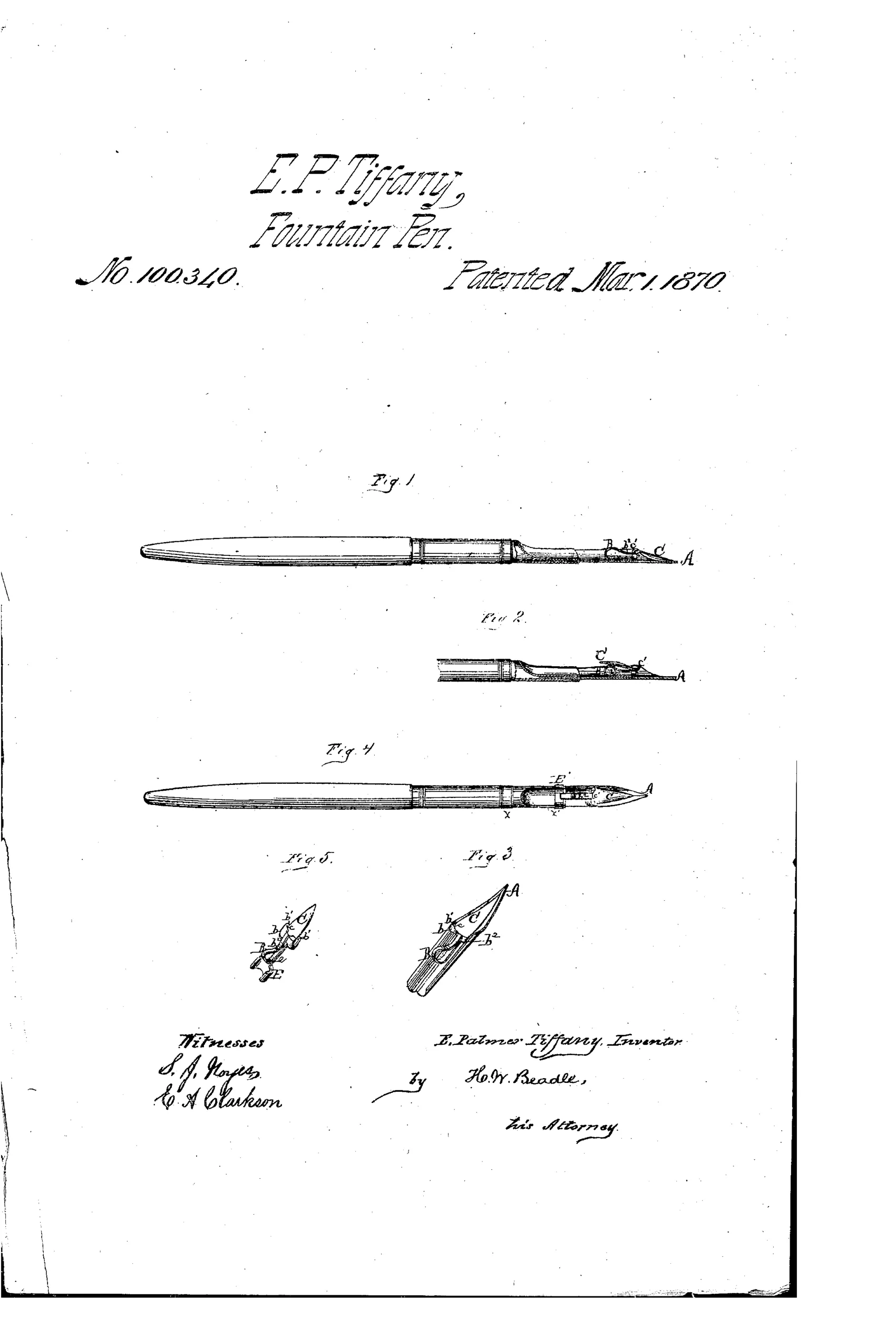
Fountain pen with hinged ink-reservoir flap
✒ How it works
The pen A carries a metallic strip B whose ears form bearings for the pivots of a hinged, slightly concave flap C, which forms the ink fountain beneath the pen. A spring b2, formed as part of strip B, presses against a downward projection on the flap to hold it closed and guard against ink loss or rattling. The flap can be swung back on its pivots for cleaning, and the entire fountain assembly can be attached either directly to the pen or, via a band E and strip e, to the holder, making it detachable and interchangeable.
✒ What was claimed
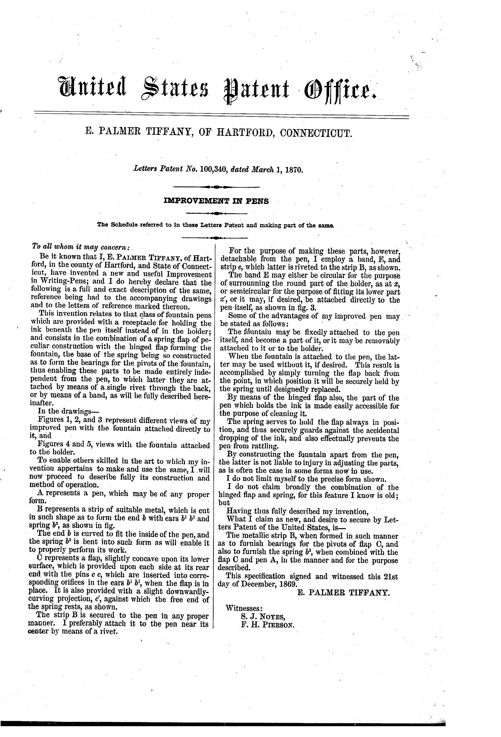
“The metallic strip B, when formed in such manner as to furnish bearings for the pivots of flap C, and also to furnish the spring b2, when combined with the flap C and pen A, in the manner and for the purpose described.”
In plain English: The claim covers a single metal strip that both holds the pivots for the hinged ink-flap and acts as its spring, combined with the flap and the pen.
✒ In the inventor’s words
“By constructing the fountain apart from the pen, the latter is not liable to injury in adjusting the parts, as is often the case in some forms now in use.”— E. Palmer Tiffany, from the specification
Fate unknown
Reservoir attachments of this type were sold by various makers in the era, but no Tiffany-marked example is documented; a surviving specimen would settle it.
✒ Commentary
This is not really a fountain pen in the modern sense — it's a reservoir attachment, a little concave metal flap pivoted beneath an ordinary nib to hold a charge of ink. That puts it squarely in the pre-Waterman stratum: dozens of inventors were trying to make a dip pen write longer without solving the problem Waterman finally cracked in 1884, which was controlled air exchange. Tiffany doesn't touch that problem at all. His ink is held by surface tension against the underside of the pen, and gravity plus capillarity does the rest, for better or worse.
What he does solve, and rather neatly, is maintenance. Look at Fig. 3: the strip B is one piece of metal doing three jobs — it mounts to the nib, its ears form the pivot bearings, and a tongue bent out of it becomes the spring b2 that snaps the flap shut. The whole fountain hinges back like a trapdoor for cleaning, which anyone who has scraped dried ink out of a reservoir attachment would appreciate. His best line is telling: prior fountains bent the nib when you fiddled with them. Fig. 4 shows the second idea — mount the assembly on the holder via band E, so the fountain becomes interchangeable across nibs.
It's a tidy piece of sheet-metal engineering aimed at a problem the whole approach couldn't escape: no flow regulation means blots and starvation. A refinement of a dead end, executed with care.
Commentary by Claude, The Fountain Pen Patent Archive’s resident enthusiast