The Fountain Pen Patent Archive

The instruments that put ink under pressure

Fountain pen

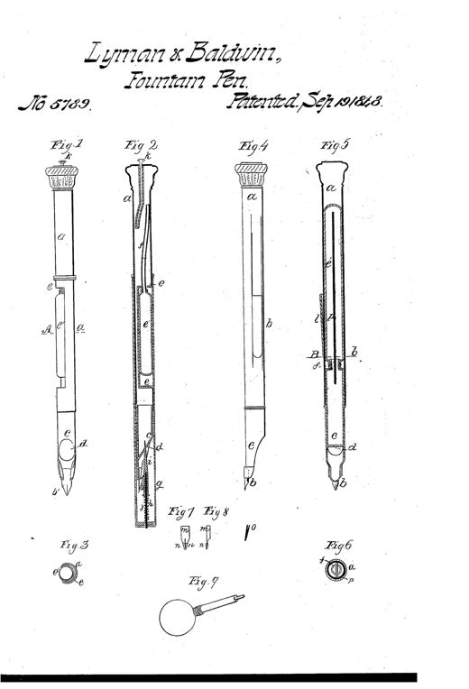
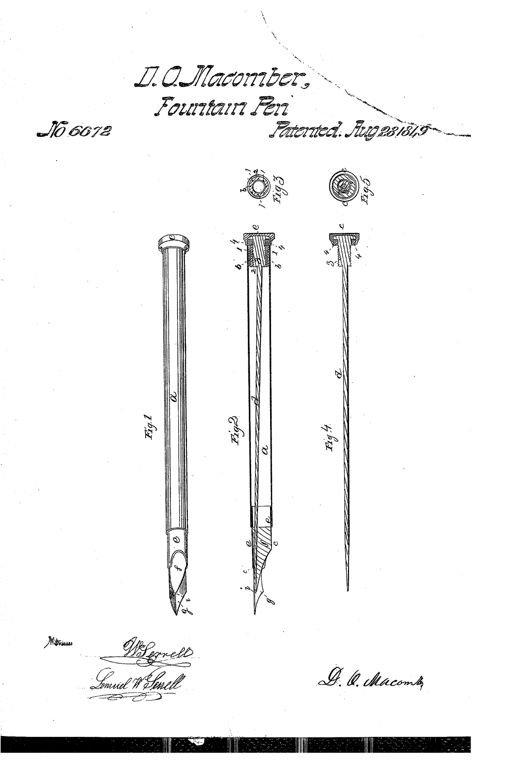
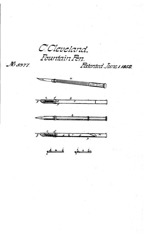
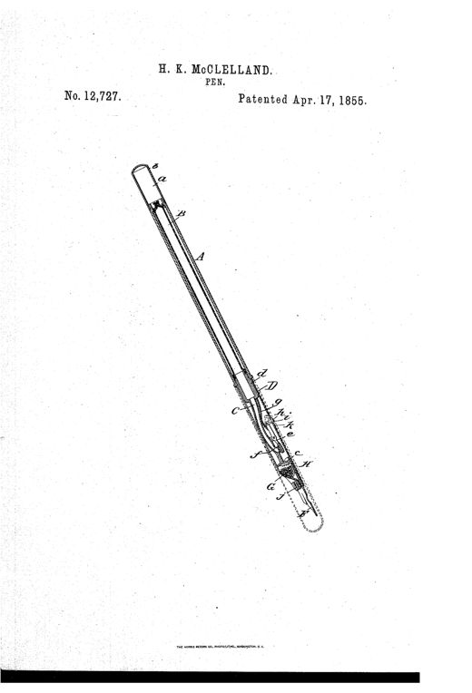
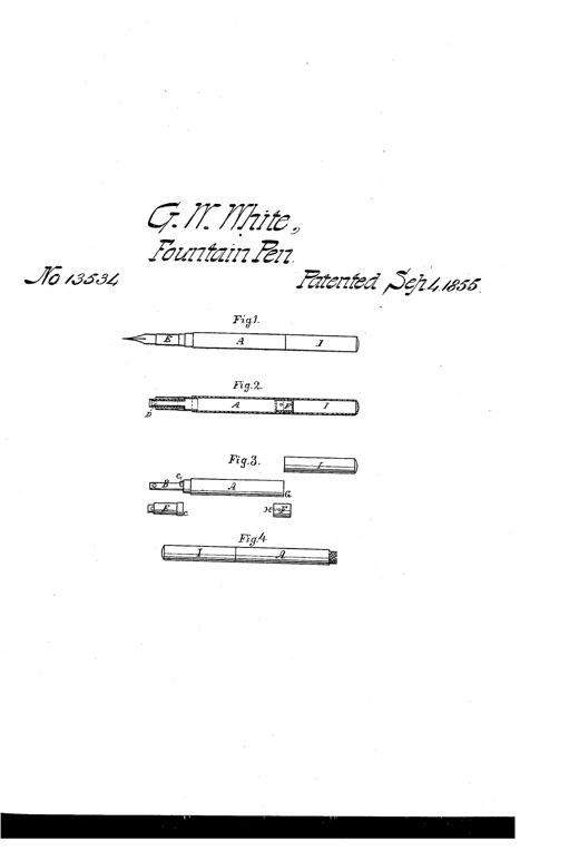
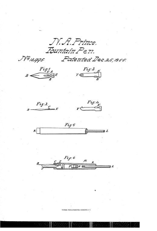
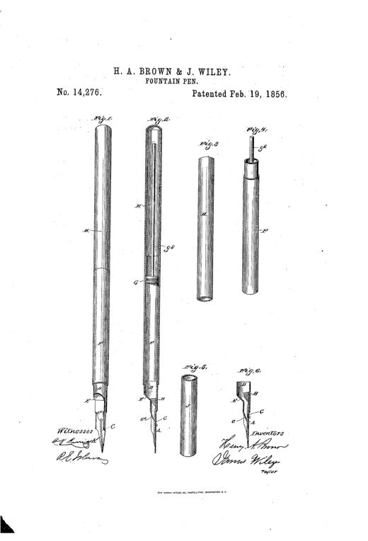
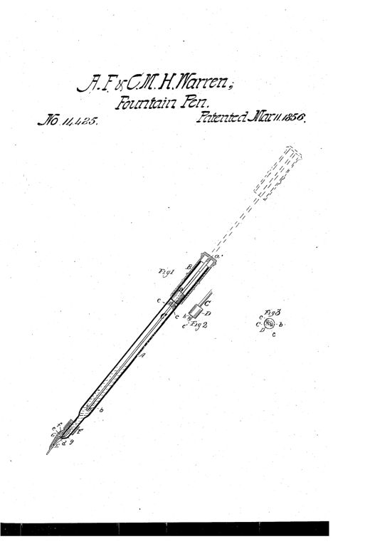
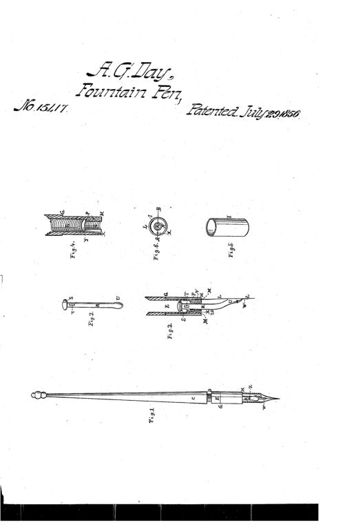
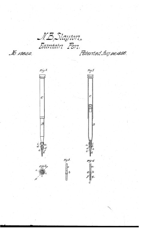
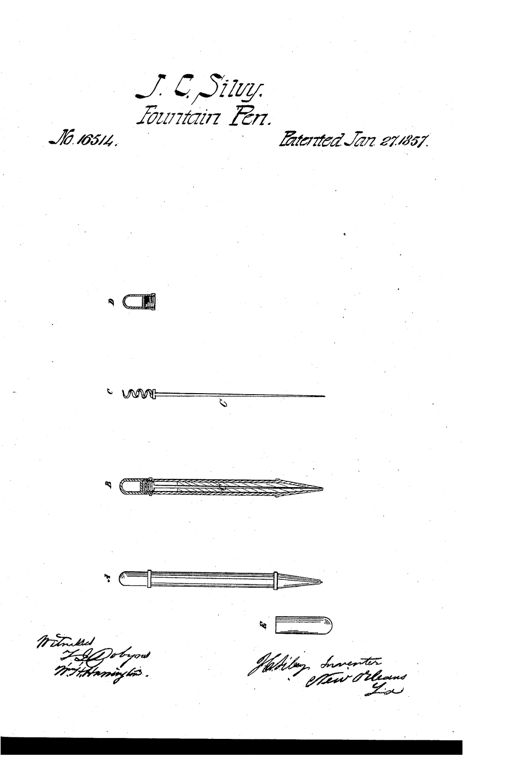
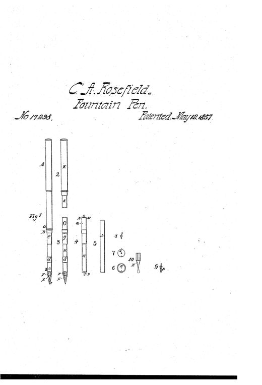
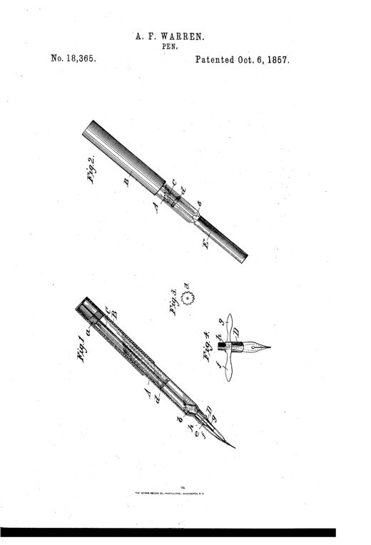
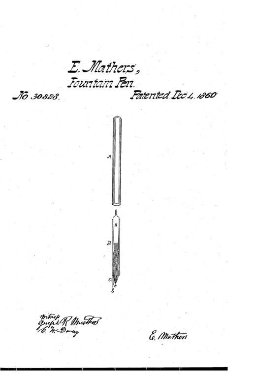
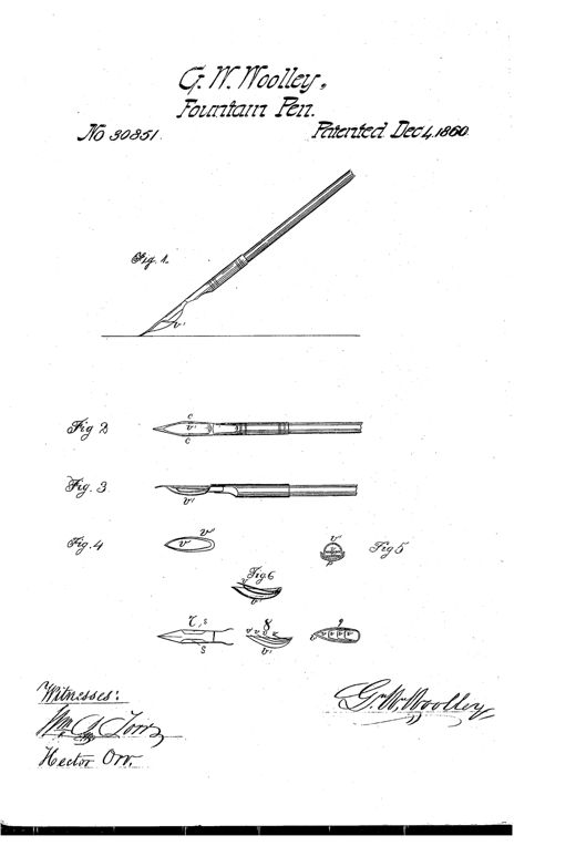
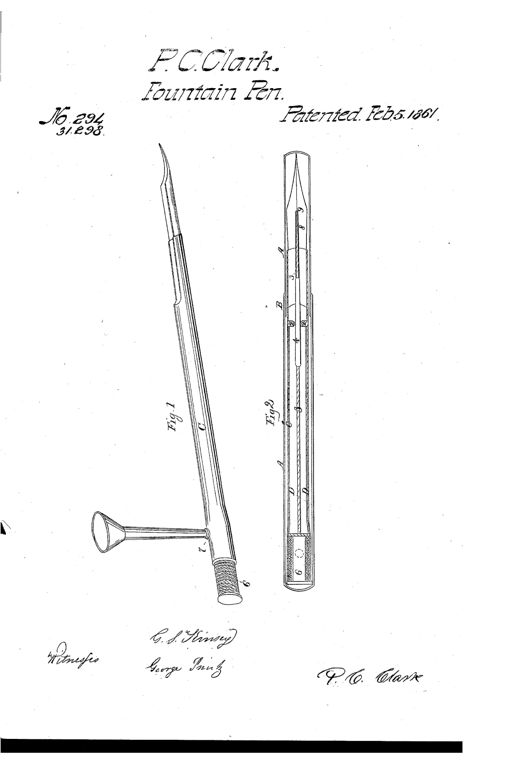
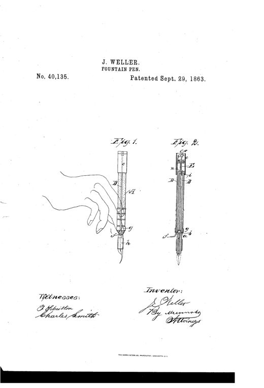
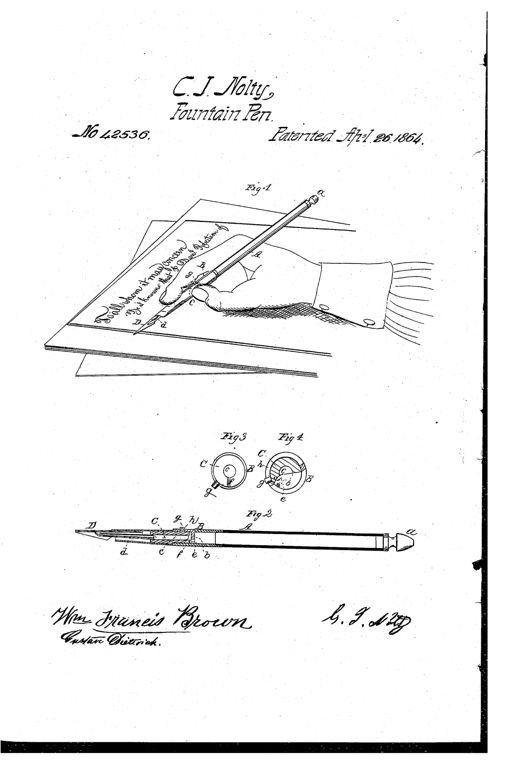
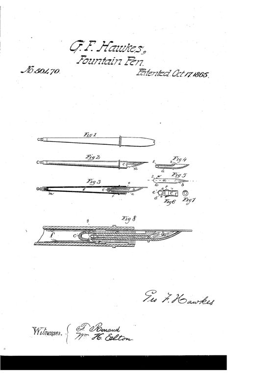
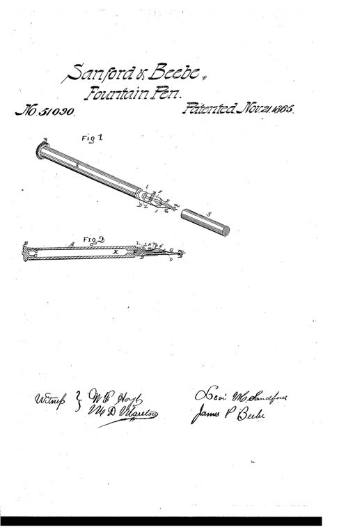
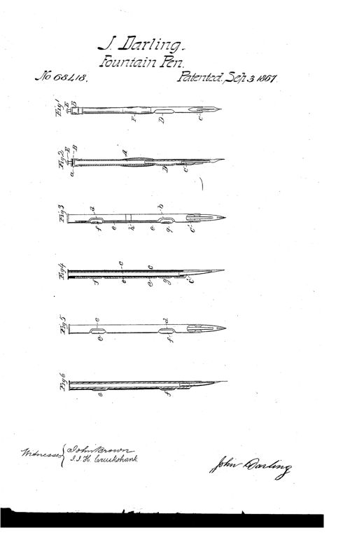
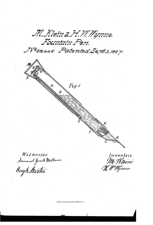
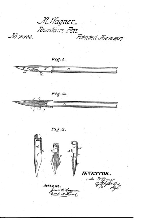
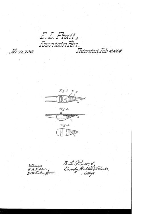
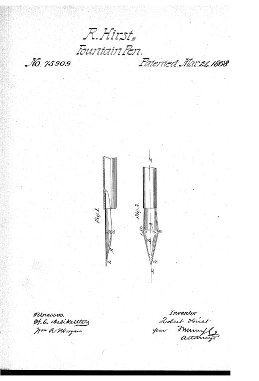
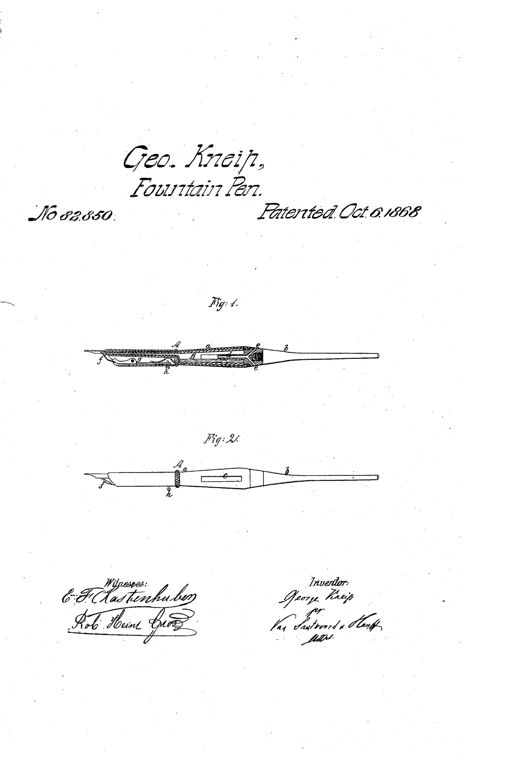
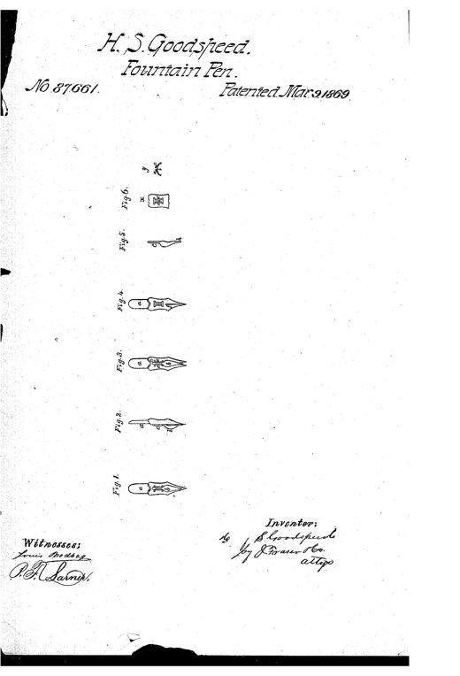
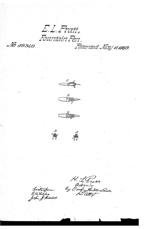
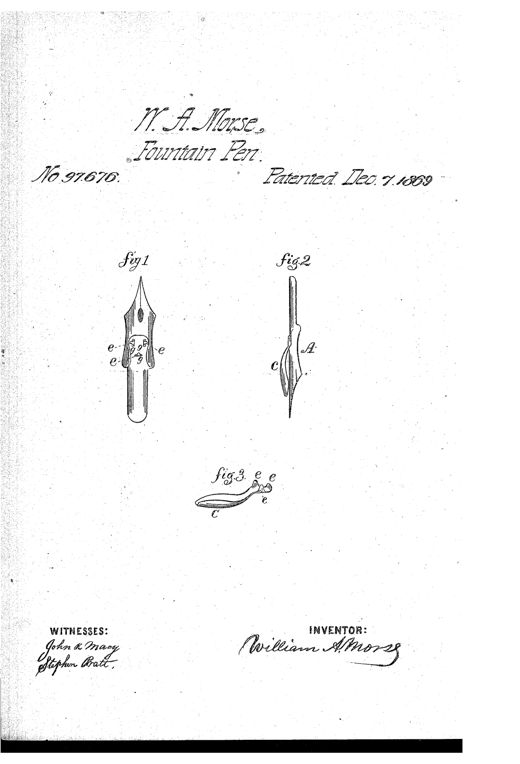
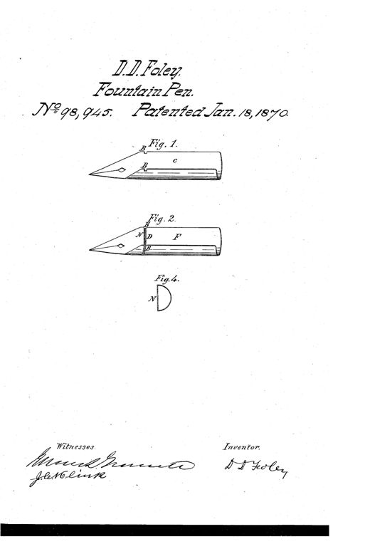
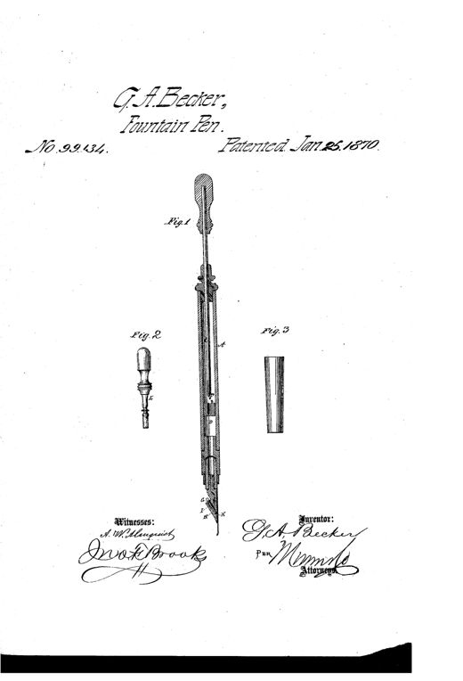
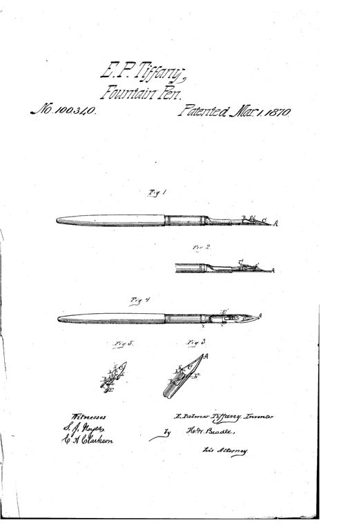
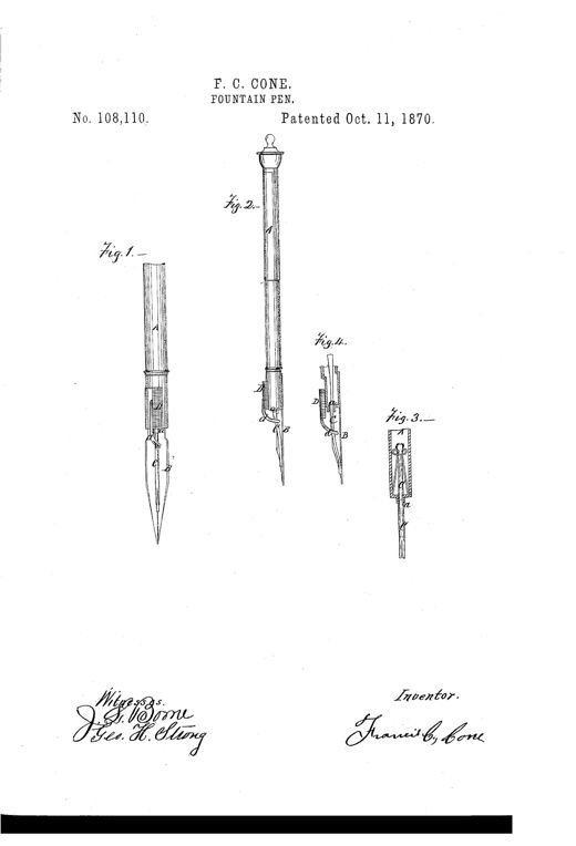
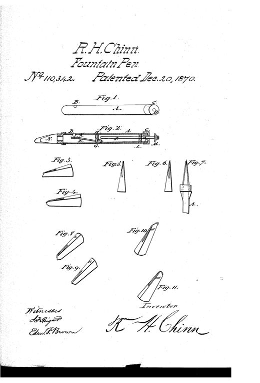
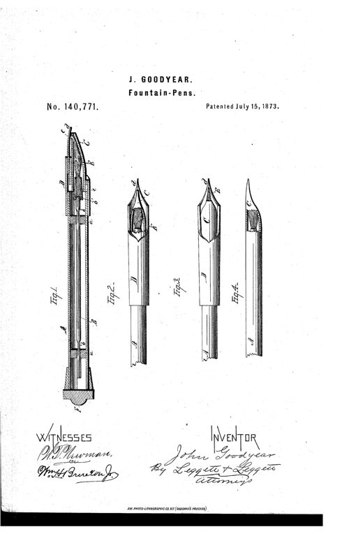
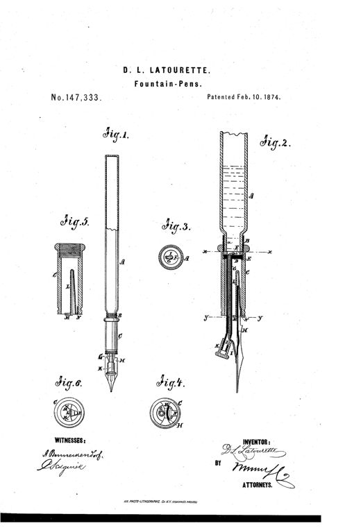
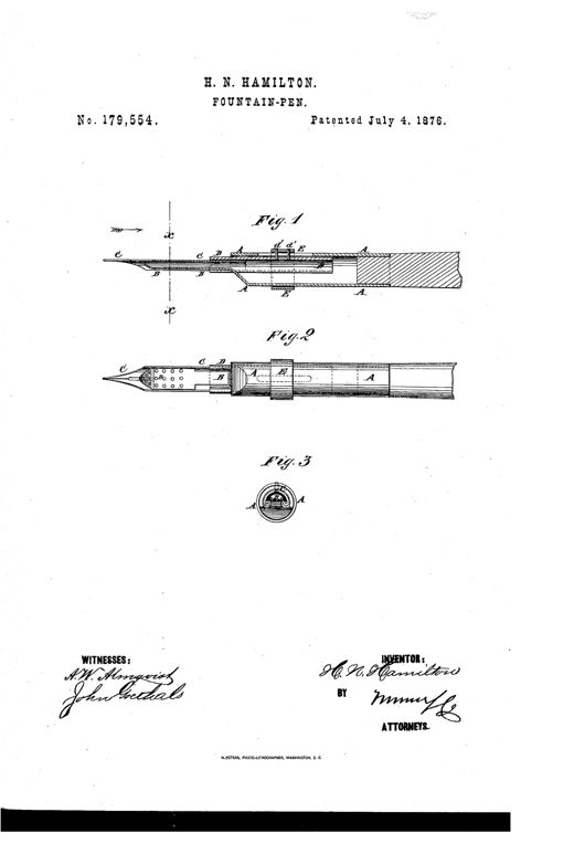
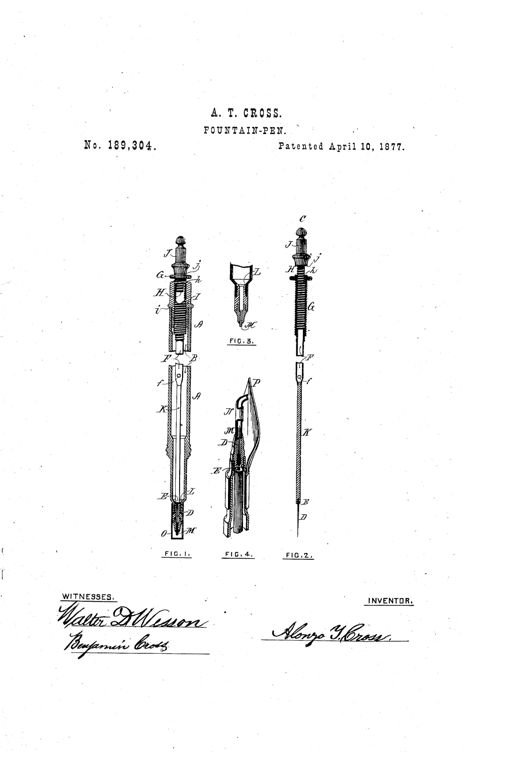
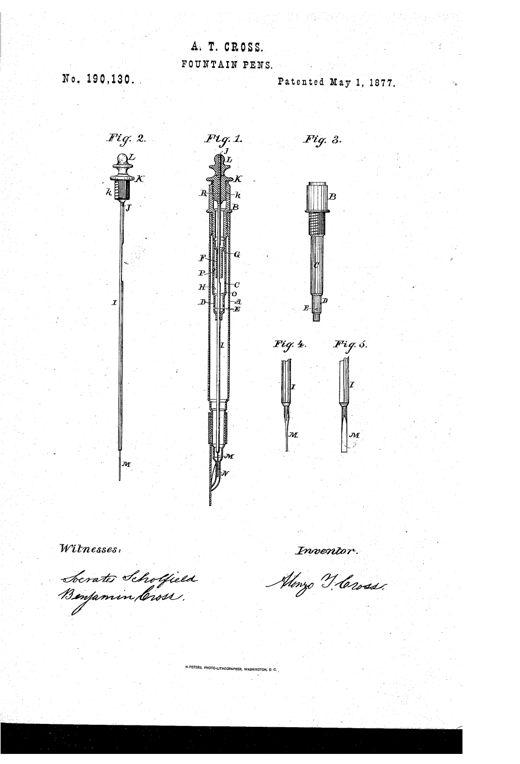
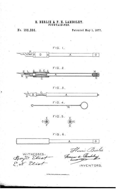
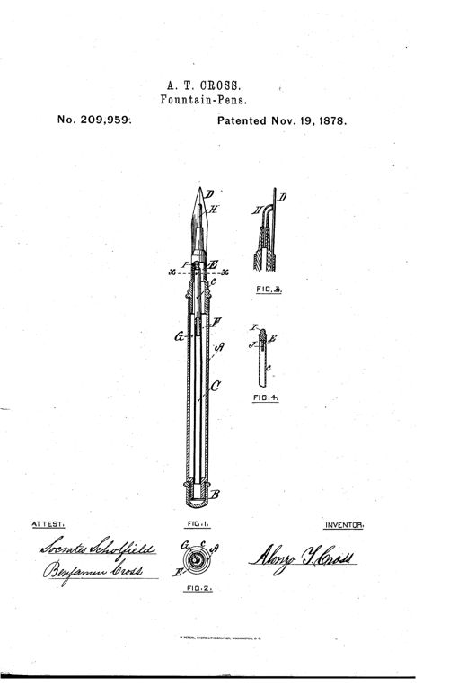
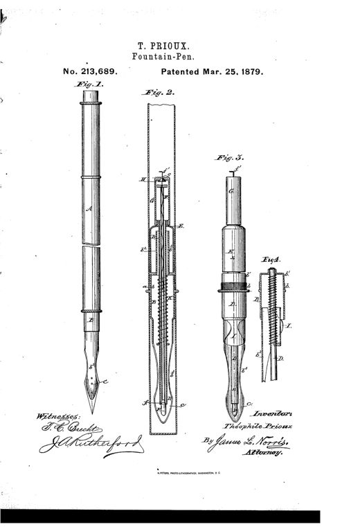
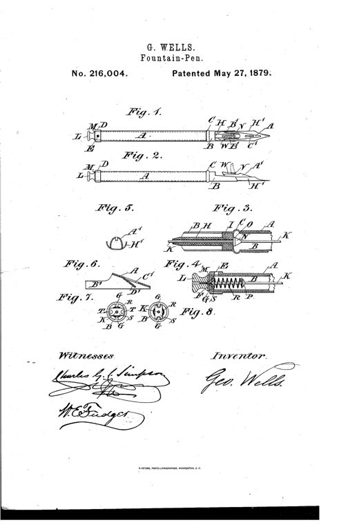
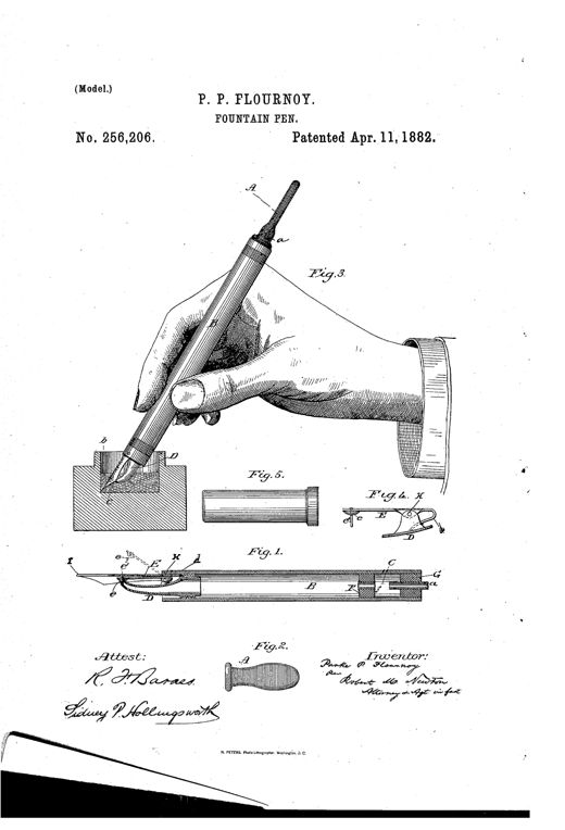
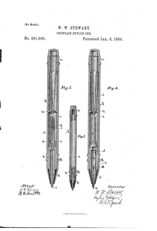
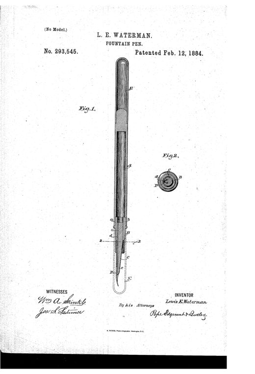
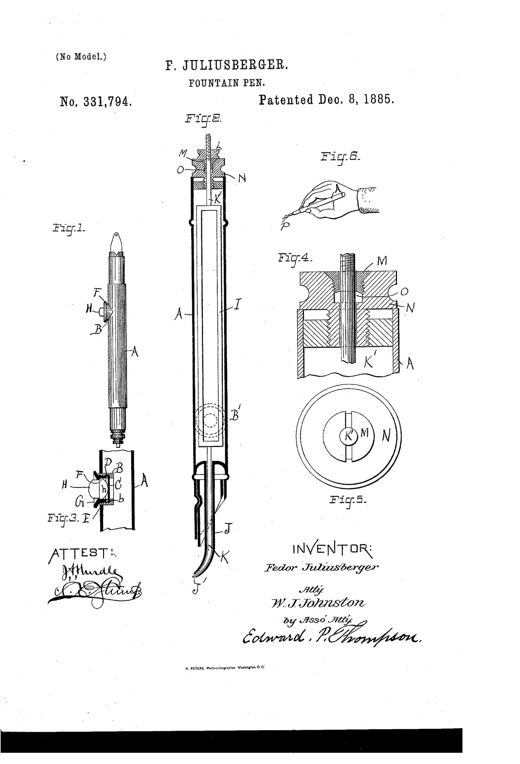
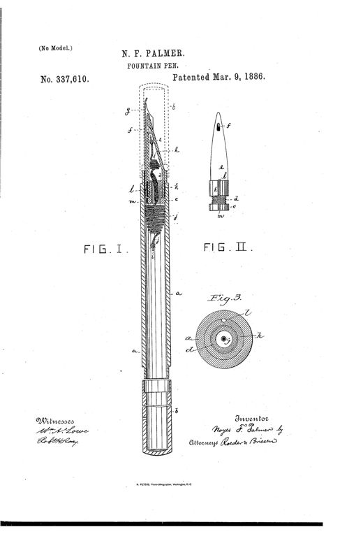
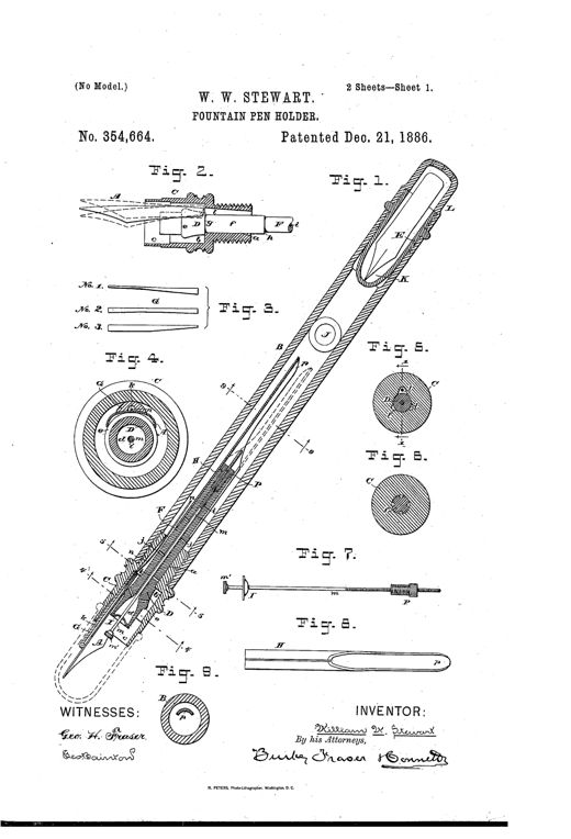
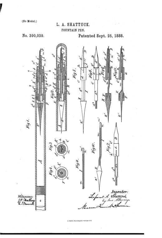
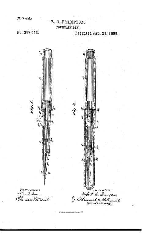
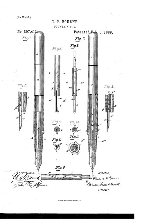
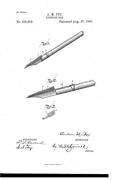
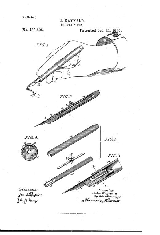
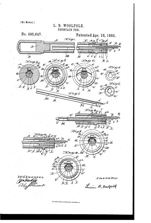
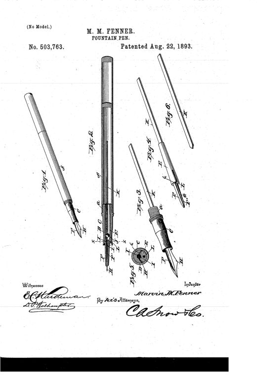
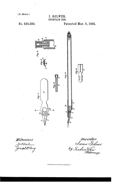
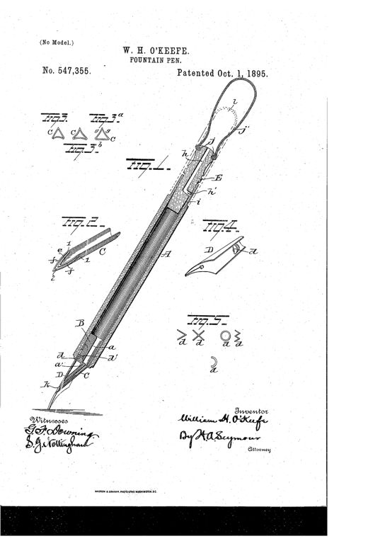
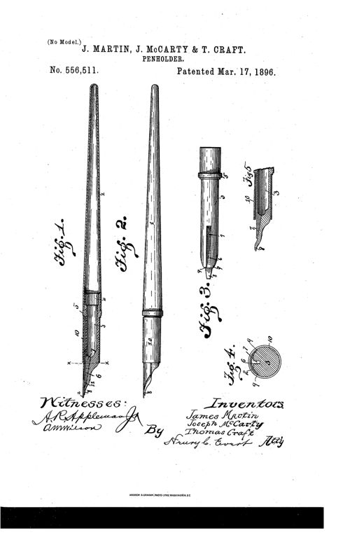
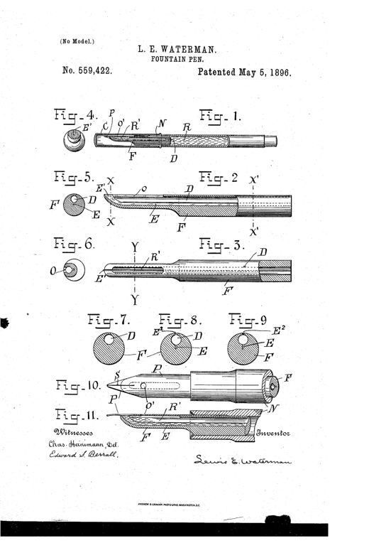
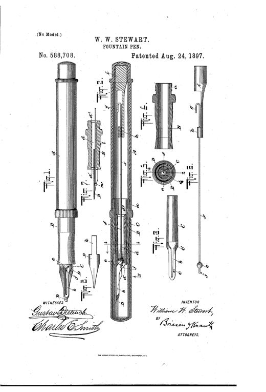
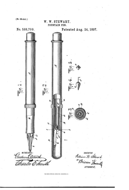
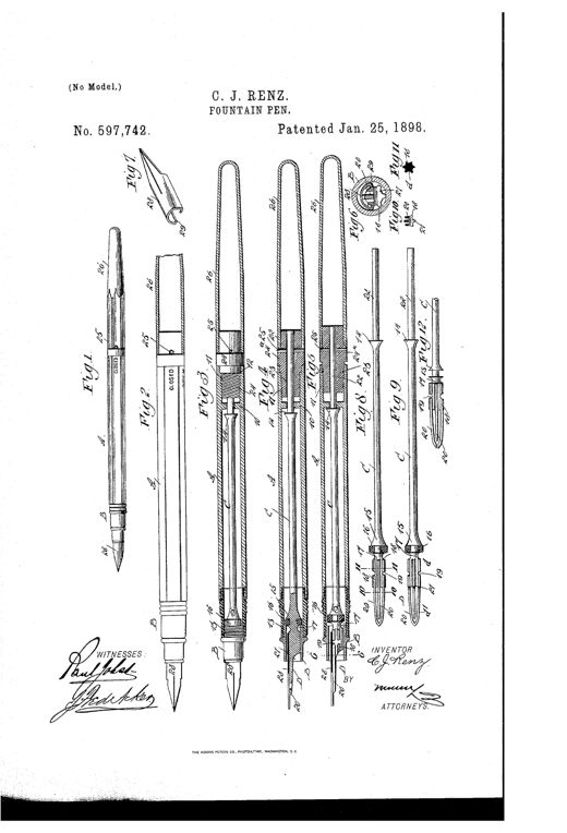
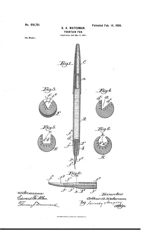
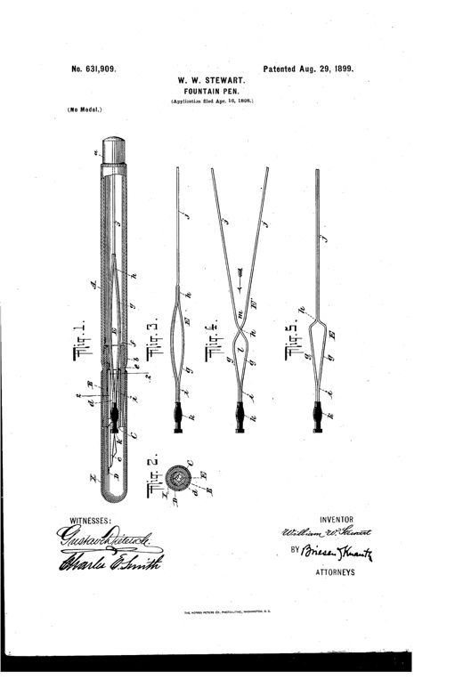
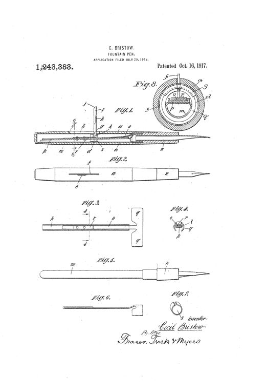
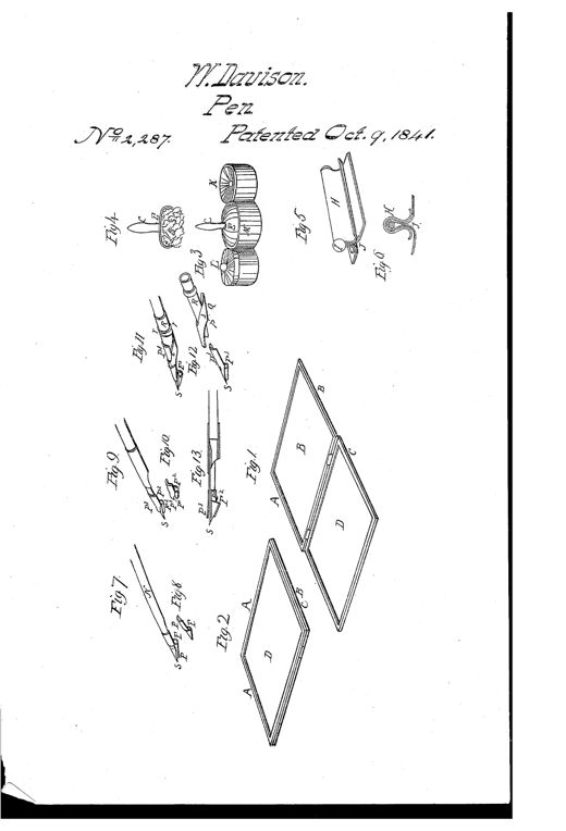
Patent drawing sheet showing a hinged rectangular writing-guide frame with glass panel, a spherical sponge holder, a cylindrical roller drier, and several quill and metallic fountain pens with folded sheath plates and nibs.ART OF WRITING BY A CONSTRUCTION OF FOUNTAIN-PEN ADAPTED TO WRITING ON A GUIDE FORMED OF GROUND GLASS, &c.William Davison · October 9, 1841Line drawings of an 1848 fountain-pen holder showing an exterior view with cap and nib, an internal longitudinal cross-section revealing the india-rubber ink bag and cap-tube spring plug, a small cross-section of the bag recess, alternate cylindrical holder designs, close-up front and edge views of the quill nib with metal tip, and a separate india-rubber bulb ink pump.IMPROVEMENT IN FOUNTAIN-PEN HOLDERS AND NIBSAzel S. Lyman and Matthias W. Baldwin · September 19, 1848Patent drawing of a 19th-century fountain pen showing a full perspective view with nib and cap (Fig. 1), a longitudinal cross-section revealing an internal conical valve and wire (Fig. 2), and small end-on views of the threaded cap and feed mechanism (Figs. 3-5).IMPROVEMENT IN FOUNTAIN-PENS.David O. Macomber · August 28, 1849Patent drawing showing a fountain pen labeled 'READY WRITER' in full assembled view, plus cross-sections and detail views of the internal rod, conical valves, spring, and slide mechanism inside the hollow pen holder.IMPROVEMENT IN FOUNTAIN PEN-HOLDERSCharles Cleveland · June 1, 1852A patent drawing of an early fountain pen shown in longitudinal cross-section, illustrating a cylindrical handle with a removable cap, an internal ink bag connected to a tapering tube with a spring-loaded valve and pressable key, and a lower holder containing a sponge that feeds ink to the pointed nib, with a protective outer case sheathing the assembly.FOUNTAIN-PENHugh K. McClelland · April 17, 1855Patent drawing showing four views of a 19th-century fountain pen holder: an assembled pen with nib and barrel labeled A, E, and I; a sectional cutaway showing internal tubes D, F, and G; an exploded view of separated parts B, C, E, F, G, H; and the pen with its protective cover I in place.FOUNTAIN-PENGeo. W. White · September 4, 1855A technical patent drawing showing a fountain pen nib with a notched heel (labeled A, B, C, D, E), a matching notched feeding-tube (A', B', T), a cylindrical main reservoir-tube (R to L), and a cross-section of the assembled pen with piston-rod and piston-head (P, M, N) inside the barrel.IMPROVEMENT IN FOUNTAIN-PENS.Newell A. Prince · December 25, 1855Patent drawing of an 1856 fountain pen showing six figures: an assembled pen and case, a cutaway with internal piston and rod, separate case sections, and detailed close-ups of the nib and slide-valve mechanism at the pen tip.IMPROVED FOUNTAIN-PENHenry A. Brown and James Wiley · February 19, 1856Patent drawing of an early fountain pen showing a long tapered tube with a cap and internal rod at top, an ink reservoir plate and nib at the bottom, with two small detail views of the piston's underside labeled Fig. 2 and Fig. 3.FOUNTAIN-PENA. F. Warren and C. M. H. Warren · March 11, 1856Technical patent drawing showing a slender fountain pen with an internal sliding feed-tube mechanism, valve-seat, and metallic nib, illustrated in six labeled cross-sectional and external views.IMPROVED FOUNTAIN-PENAustin G. Day · July 29, 1856Patent drawing of a cylindrical fountain pen with a slitted tapering metal point, showing an assembled outside view, an end view, a cross-section revealing an internal ink reservoir and cap, and a detached tube with the point spread open into separate nibs.FOUNTAIN-PENNelson B. Slayton · August 26, 1856Patent drawing showing five views labeled A through E of an early fountain pen: the assembled pen (A), a sectional view revealing internal parts (B), the central guide rod with a coiled spring (C), a small threaded cap (D), and a protective shield for the pen's point (E).FOUNTAIN-PEN.Joseph C. Silvy · January 27, 1857Patent drawing showing a disassembled 19th-century fountain pen with labeled parts including barrel sections, quill conductor, nib, and small hardware components like screws and disks.IMPROVEMENT IN FOUNTAIN-PENSCharles Adolphus Rosefield · May 12, 1857Patent drawing showing a cylindrical fountain pen with an internal rod-and-valve mechanism, a sliding outer sleeve, a screw-in nib holder with two pivoted side plates, and a protective cap tube, along with detail views of the serrated cut-off valve and the nib assembly.FOUNTAIN-PEN.A. F. Warren · October 6, 1857Patent drawing showing a hollow cylindrical pen holder labeled A above, and below it an assembled writing implement with a brush labeled B inserted into a holder labeled A, tapering to a pen point labeled C with nib details e and g.IMPROVEMENT IN FOUNTAIN-PENSEbenezer Mathers · December 4, 1860Technical patent drawing of a dip pen with an ink reservoir attachment clasped to its underside, shown in full assembled view (Fig. 1) and in several detail cross-sections of the nib, valves, and clasping sides (Figs. 2-9).FOUNTAIN-PENG. W. Woolley · December 4, 1860Patent drawing of an 1861 fountain pen showing an external perspective view with a pointed nib and threaded grip attached to a small funnel, alongside a longitudinal cross-section revealing an internal conducting rod, valve, and piston mechanism running the length of the pen holder.IMPROVEMENT IN FOUNTAIN-PENSP. C. Clark · February 5, 1861Two patent drawings of a 19th-century fountain pen: Figure 1 shows a hand holding the assembled pen with a tapering nib, and Figure 2 shows a cutaway internal view revealing a central rod, conical stopper, rocking lever, spring, and air-vent plug mechanism inside a tubular case.FOUNTAIN-PENJoseph Weller · September 29, 1863A patent drawing showing a hand holding a fountain pen writing on paper, with detailed cross-section and valve component diagrams labeled with letters A through h.FOUNTAIN-PENG. J. Nolty · April 26, 1864Patent drawing of an 1865 fountain pen showing the assembled instrument, an internal cross-section revealing a sliding tubular feeder and thimble-like stopper, and detail views of the spoon-shaped feeder tip that contacts the underside of the nib.FOUNTAIN-PENGeorge F. Hawkes · October 17, 1865Patent drawing of an 1865 fountain pen showing an exterior perspective view (Fig. 1) with a threaded cap, tapered barrel, and nib assembly, and a sectional side view (Fig. 2) revealing the internal ink fountain, pipe, lever, and spring mechanism labeled with letters A through S.FOUNTAIN-PEN.Levi M. Sandford, James P. Beebe · November 21, 1865A sequence of six technical line drawings showing the underside plan and longitudinal cross-sections of a 19th-century fountain pen holder, each labeled with letters marking the reservoir, elastic tube, distributing tube, nib, and thumb-plate components.RESERVOIR PEN-HOLDERJohn Darling · September 3, 1867A diagonal cross-section drawing of an antique fountain pen showing internal parts labeled A through M, including an ink chamber, spring valve, rod, and pen point.FOUNTAIN-PEN.M. Klein and Henry W. Wynne · September 3, 1867Patent drawing of a 19th-century fountain pen showing an assembled exterior view, an internal cross-section revealing a bristle-filled ink channel, and separated parts including a metal sheath, winged bristle socket, and pen nib.IMPROVEMENT IN FOUNTAIN-PENS.Michael Wagner · November 12, 1867Patent drawing showing a pen nib with an attached perforated metal ink reservoir, including a top view, a cross-section, and a plan view of the detached reservoir.IMPROVEMENT IN PENSE. L. Pratt · February 18, 1868Two line drawings of a pen nib: Fig. 1 shows a side section of the pen with a curved hinged flap along its concave underside, and Fig. 2 shows an inner view of the nib with the flap labeled B, pivot points marked c and c, and the nib point marked b.IMPROVEMENT IN PENS.Robert Hirst · March 24, 1868Two technical line drawings of a fountain pen: Figure 1 shows a longitudinal cross-section revealing an internal glass ink cistern, central air tube, and spring valve with a thumb button, while Figure 2 shows the same pen's exterior side view with a tapered nib and cylindrical barrel.IMPROVEMENT IN FOUNTAIN-PENS.George Kneip · October 6, 1868Patent drawing showing six figures of a steel dip pen nib with an attached spoon-shaped metal reservoir on its back, including plan and side views, a detached spoon piece, and cross-sectional details of the sliding attachment mechanism.IMPROVEMENT IN PENSHenry S. Goodspeed · March 9, 1869Patent drawing showing five small views (A through E) of a metal pen-fountain device: elongated tapered tongue pieces with perforated, dotted textured surfaces labeled with letters a, b, c, e, f, illustrating front, rear, side, bottom, and top views of the fountain clasped around a pen nib and shank.IMPROVEMENT IN PENS.E. L. Pratt · May 11, 1869Patent drawing of a steel dip-pen nib with a curved fountain spring inserted through slots and its ends bent over to hold it in place, shown from front, side, and as a separate spring piece.IMPROVEMENT IN PENSWilliam A. Morse · December 7, 1869Patent drawing showing a pen nib in Fig. 1 with notches labeled B B, Fig. 2 showing the same nib fitted with a rubber ring N and ink channel D, and Fig. 4 showing a small half-moon shaped rubber ring labeled N.IMPROVEMENT IN PENSD. D. Foley · January 18, 1870Patent drawing showing a slender hard rubber fountain pen in cross-section with an internal piston rod, threaded valve mechanism, and a separate key and cap shown alongside.IMPROVEMENT IN FOUNTAIN-PENSG. A. Becker · January 25, 1870Patent drawing showing a slender cylindrical fountain pen holder with a pointed nib assembly at one end featuring a small hinged flap and spring mechanism labeled with letters A, B, C, and E, shown in five different views including full-length side views and close-up details of the nib and flap components.IMPROVEMENT IN PENSE. Palmer Tiffany · March 1, 1870Patent drawing of a slender fountain pen holder with a knobbed cap, showing four figures: full-length exterior views (Figs. 1 and 2) with an internal elastic strip and finger slide near the nib, and two cross-sectional close-ups (Figs. 3 and 4) illustrating the valve strip in closed and open positions.IMPROVEMENT IN FOUNTAIN-PENS.Francis C. Cone · October 11, 1870Patent drawing showing a cylindrical fountain pen holder in longitudinal section with internal spring, valve, and piston mechanisms, alongside eight small perspective views of a four-sided pen point labeled Figures 3 through 11, each showing a different facet or angle of the nib used for varying handwriting styles.IMPROVEMENT IN PENSRichard H. Chinn · December 20, 1870Patent drawing showing a longitudinal cross-section of a fountain pen with a valve rod running through a tube, alongside three separate detail views of pen-point tips with brush tufts inside tapered nib holders.IMPROVEMENT IN FOUNTAIN-PENSJohn Goodyear · July 15, 1873Patent drawing of a 19th-century fountain pen showing a glass ink-fountain handle screwed to a tubular base with a nib, feed tube, wick, and adjustable cap, alongside cross-sections labeled with reference letters A through N.IMPROVEMENT IN FOUNTAIN-PENSDavid L. Latourette · February 10, 1874Technical patent drawing showing a fountain pen in longitudinal section with labeled parts including tube A, tongue B, nib C, holder D, and ring E, alongside a front view and a small circular cross-section diagram.IMPROVEMENT IN FOUNTAIN-PENSHenry N. Hamilton · July 4, 1876Patent drawing showing four figures of a fountain pen: a full longitudinal cross-section labeled Fig.1 with threaded cap, needle, valve, and tapering writing tube; a similar full pen view labeled Fig.2 showing the internal rod and needle; an enlarged detail of the tubular point and valve seat labeled Fig.3; and a side view labeled Fig.4 showing the needle and capillary tube feeding an ordinary pen nib.IMPROVEMENT IN FOUNTAIN-PENSAlonzo T. Cross · April 10, 1877Patent drawing of a 19th-century fountain pen shown in cross-section (Fig. 1) revealing an inner valve-spindle, air-tube, and nested chambers, with separate views of the cap and threaded nut assembly (Fig. 2), the outer air-tube (Fig. 3), and close-up edge and side views of a flattened ink needle (Figs. 4 and 5).IMPROVEMENT IN FOUNTAIN-PENSAlonzo T. Cross · May 1, 1877Patent drawing showing six figures of a fountain pen holder, including a longitudinal cross-section revealing an internal ink reservoir, elastic rubber chamber, connecting rod, curved ink delivery tube to the nib, a plunger with hooked wire for filling, and a protective cap for the pen point.IMPROVEMENT IN FOUNTAIN-PENSHenri Berlie and François X. Lamboley · May 1, 1877Patent drawing of a 19th-century fountain pen in longitudinal section showing the nib, air-tube, ink reservoir, and vent cap, with side cross-section views of the adjustable tube components.Improvement in Fountain-PensAlonzo T. Cross · November 19, 1878Patent drawing showing a fountain pen in full elevation and in cross-section, revealing an internal tube-and-valve mechanism with a spiral spring, a spoon-shaped ink bowl, and a metal nib point.IMPROVEMENT IN FOUNTAIN-PENSThéophile Prioux · March 25, 1879Patent drawing of a Victorian-era fountain pen showing the barrel, sliding tubes, internal valve mechanism, nib assembly, and a curved metal fountain attachment clipped beneath the pen point, with cross-sectional detail views of the pump and valve components.IMPROVEMENT IN FOUNTAIN-PENSGeorge Wells · May 27, 1879Patent drawing showing a hand dipping a fountain pen's feeder tip into an inkstand while compressing a rubber bulb at the pen's top, alongside smaller cutaway diagrams of the pen barrel, ink-regulator bar and spring, rubber filling bulb, and protective cap.FOUNTAIN-PEN.Parke P. Flournoy · April 11, 1882Patent drawing of a fountain stylus pen showing three longitudinal cross-sections labeled Fig. 1, Fig. 2, and Fig. 3, each revealing an internal ink reservoir, condensing chamber, spring mechanism, and a fine pointed stylus tip enclosed in a jacket.FOUNTAIN STYLUS-PEN.William W. Stewart · January 8, 1884Patent drawing of an 1884 Waterman fountain pen shown in longitudinal cross-section, revealing the ink barrel, feed bar with a grooved channel, nib, and protective cap, alongside a small circular cross-section diagram labeling the groove and fissures.FOUNTAIN-PEN.Lewis E. Waterman · February 12, 1884Patent drawing sheet showing a slender fountain pen in full profile, a cutaway sectional view revealing an internal sliding frame with needle valve and threaded gland-screw packing box, a close-up of the finger button and diaphragm, a top view of the concentric packing components, and a small sketch of a hand holding the pen while writing.FOUNTAIN-PENFedor Juliusberger · December 8, 1885Patent drawing of a 19th-century fountain pen shown in cross-section (Fig. I) with labeled parts a, b, c, d, i, j, k, l, m, an enlarged detail of the plug and tip (Fig. II), and a cross-sectional end view of the collar (Fig. 3).FOUNTAIN-PEN.Noyes F. Palmer · March 9, 1886Patent drawing of a hard rubber fountain pen holder shown in full longitudinal section with labeled internal parts including the nib, nozzle, wedge key, ink ducts, condensing chamber, and cap, alongside smaller cross-sectional and detail figures of the mechanism.FOUNTAIN PEN-HOLDER.William W. Stewart · December 21, 1886Patent drawing of a fountain pen showing a long central section labeled A with a detailed nib and feed assembly at the tip, plus smaller cross-section and modification diagrams labeled Figs. 2 through 11.FOUNTAIN-PEN.Laforest A. Shattuck · September 25, 1888Two vertical patent drawings of a hard rubber fountain pen in longitudinal section, one shown open with the point exposed and internal flexible tube and compressor visible, the other shown with the protective cap fitted over the nib end, with lettered parts labeling the barrel, tube, compressor, and nib.FOUNTAIN-PEN.Robert Christopher Frampton · January 29, 1889Patent drawing showing two long fountain pen assemblies with labeled parts (barrel A, tube B, cap D, feeder F, pen E) alongside small cross-sectional diagrams of the feeder bar showing spiral and straight ink grooves.FOUNTAIN-PEN.Theodore Frederick Bourne · February 5, 1889Patent drawing of a fountain pen attachment showing a spiral coil-shaped ink reservoir wrapped around the pen shaft near the nib, secured by a collar labeled B, with a detailed close-up of the perforated coil in Figure 3.FOUNTAIN-PENAndrew M. Fox · August 27, 1889Patent drawing showing a hand gripping a cylindrical fountain pen while writing, with additional cutaway diagrams revealing the internal elastic ink reservoir, presser bar, thumb button, locking nut, and eccentric plug holding the pen nib.FOUNTAIN-PENJohn Raynald · October 21, 1890Patent drawing of a fountain pen showing the barrel, plug, tubular point section, nib, feed rod with feed-tongue, and several cross-sectional and perspective views labeled with reference letters.FOUNTAIN-PENLucien B. Woolfolk · April 18, 1893Patent drawing showing six views of a hard rubber fountain pen: a full assembled pen with tapered nib, a cross-sectioned barrel revealing the internal feed plug and ball valve mechanism, an enlarged feed plug with detachable nozzle, the same feed plug separated with pen point removed, a circular cross-section showing the slit and grooves, and a thin flat auxiliary conductor reed.FOUNTAIN-PEN.Marvin M. Fenner · August 22, 1893Patent drawing of a fountain pen showing a long cylindrical holder with a screw cap at top, an internal reservoir tube, and an enlarged detail of a split nib with rearward projections connected to a small elastic tube.FOUNTAIN-PEN.Iwan Golwer · March 5, 1895Patent drawing of a hard rubber fountain pen shown in full diagonal view with a cutaway section revealing the internal feed-bar, pen-point, and plug-valve, alongside smaller detail views of the triangular feed-bar cross-sections and the pen-point's locking projection.FOUNTAIN-PEN.William H. O'Keefe · October 1, 1895Patent drawing showing a tapered fountain penholder in side and sectional views, with a detailed close-up of the tubular feeder featuring a slotted tongue and a cross-section of the pen tip assembly.PENHOLDER.James Martin, Joseph McCarty, Thomas Craft · March 17, 1896Technical patent drawing of a fountain pen's feed-bar mechanism, showing longitudinal and cross-sectional views labeled with letters D, E, F, N, O, P, R marking the duct, capillary fissure, reservoir, nozzle, and nib, with the inventor's signature 'Lewis E. Waterman' at bottom.FOUNTAIN-PEN.Lewis E. Waterman · May 5, 1896Patent drawing showing eight labeled cross-sectional and detail views of a fountain pen, including the assembled holder, nib, feeder-bar with angular bore, and a small rubber ball on a wire used to regulate ink flow.FOUNTAIN-PEN.William W. Stewart · August 24, 1897Patent drawing of a hard rubber fountain pen showing the assembled pen with nib in Figure 1, a cross-sectional side view revealing the internal feeder-bar and diamond-shaped obstruction plug in Figure 2, a circular cross-section in Figure 3, and two views of a modified pyramidal obstruction plug with a hook-like finger extension in Figures 4 and 5.FOUNTAIN-PEN.William W. Stewart · August 24, 1897Patent drawing showing twelve figures of a fountain pen including full-length views, cross-sections of the barrel and valve stem, an enlarged nib perspective, and detailed plan views of the feeder and regulating valve mechanism.FOUNTAIN-PEN.Carl J. Renz · January 25, 1898Patent drawing of a fountain pen shown in longitudinal cross-section with a tapered cap, hard rubber body, and a detailed feed-bar containing a grooved ink duct, alongside five smaller circular cross-sections labeled Fig. 3 through Fig. 6 illustrating variations of the feed duct with tiny conical storage pits.FOUNTAIN-PENArthur A. Waterman · February 14, 1899Patent drawing of a fountain pen showing a long hollow barrel in cross-section (Fig.1) with an internal wire skeleton and feeder-bar, plus four smaller side views (Figs. 3-5) of alternate wire-strand skeleton configurations converging into a bow near the nib, and a round cross-section (Fig.2) showing the nested tube and skeleton arrangement.FOUNTAIN-PENWilliam W. Stewart · August 29, 1899Patent drawing showing a fountain pen barrel in longitudinal section with a pivoting lever, spring, presser plate, and ink bag, alongside a cross-sectional end view and detail views of the spring and collar components.FOUNTAIN-PENCecil Bristow · October 16, 1917