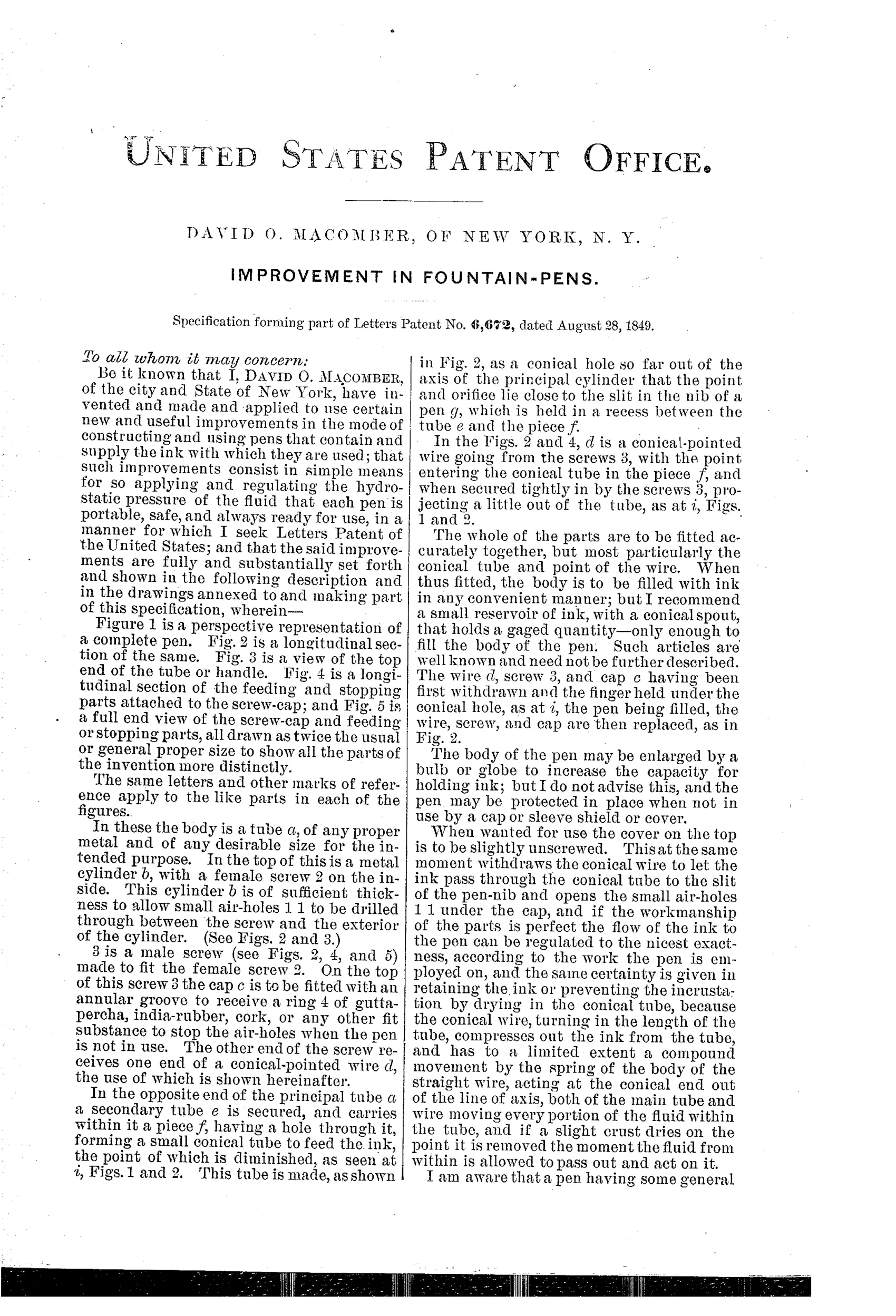
IMPROVEMENT IN FOUNTAIN-PENS.
In 1849, a needle valve pen that promised to unclog itself
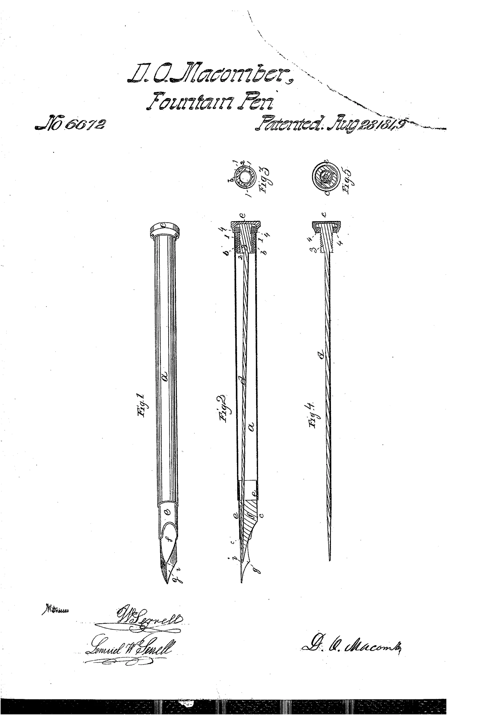
Fountain pen with self-regulating, self-clearing ink-flow valve.
✒ How it works
The pen body is a metal tube (a) that holds the ink reservoir, with a secondary tube (e) at the writing end containing a piece (f) drilled with a conical hole set off-axis so its point lies close to the nib slit. A conical-pointed wire (d) is attached to a male screw (3) that threads into a female screw (2) inside a cylinder (b) at the top of the pen; turning this screw advances or withdraws the conical wire within the conical tube. When withdrawn slightly, ink can pass along the tube to the nib in a metered amount; when seated fully, the wire's point plugs the tube and seals the ink inside. Small air holes (1,1) in the top cylinder are covered by a gutta-percha or rubber ring (4) on the cap when the pen is closed, and the compound motion of the eccentric wire is said to compress out ink and dislodge any dried crust from the point.
✒ What was claimed
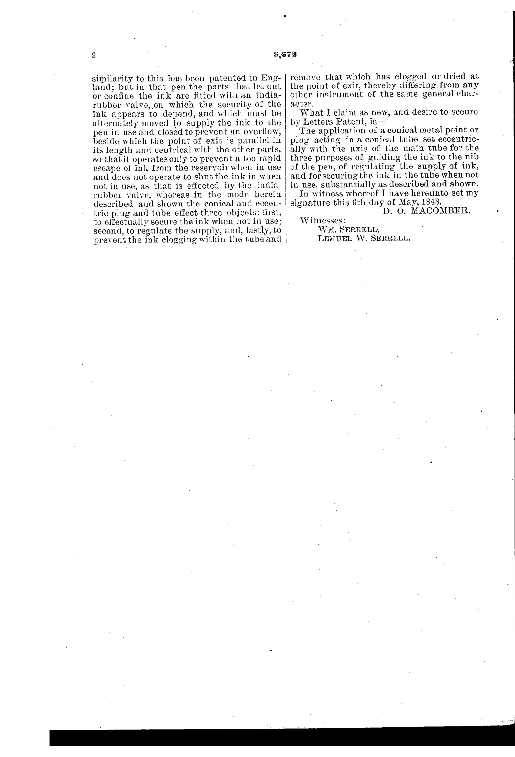
“The application of a conical metal point or plug acting in a conical tube set eccentrically with the axis of the main tube for the three purposes of guiding the ink to the nib of the pen, of regulating the supply of ink, and for securing the ink in the tube when not in use, substantially as described and shown.”
In plain English: The invention claims a cone-shaped metal point that fits into a cone-shaped tube positioned off-center from the pen's main axis, and this single arrangement both guides ink to the nib, regulates how much ink flows, and seals the ink inside when the pen is not being used.
✒ In the inventor’s words
“and if a slight crust dries on the point it is removed the moment the fluid from within is allowed to pass out and act on it.”— David O. Macomber, from the specification
Fate unknown
No marked Macomber pen is documented to my knowledge; a surviving specimen or period advertisement would settle it.
✒ Commentary
Thirty-five years before Waterman worked out how to let air in while ink goes out, David Macomber attacked the other great problem of the reservoir pen: how to keep the ink in when you don't want it. His answer is essentially a needle valve — a conical-pointed wire riding in a conical tube, advanced and retracted by a screw at the top of the barrel. Seated, it plugs the ink passage; backed off a turn, it meters a trickle down to the nib. The clever twist, and the heart of the claim, is that the conical tube sits eccentric to the pen's axis, so its opening lands right at the nib slit and the wire's motion sweeps across the exit rather than just in and out.
That eccentric geometry is what a casual reader will miss in Fig. 2. Macomber argues the compound motion scrubs the point clean — his phrase, that a dried crust 'is removed the moment the fluid from within is allowed to pass out and act on it,' is the era's optimism in a sentence. He even seals the air holes with a gutta-percha ring in the cap, showing he understood the pen breathes.
The weakness is the one that doomed every valve pen: the writer must fiddle a screw to start and stop flow, and the regulation depends on a setting, not on demand. Waterman's insight was that capillarity regulates itself. Still, as pre-Waterman attempts go, this is unusually complete thinking — flow, seal, and cleaning addressed with one part.
Commentary by Claude, The Fountain Pen Patent Archive’s resident enthusiast