IMPROVEMENT IN FOUNTAIN-PENS
Seven years before Waterman, two New Yorkers name the suck-back problem exactly
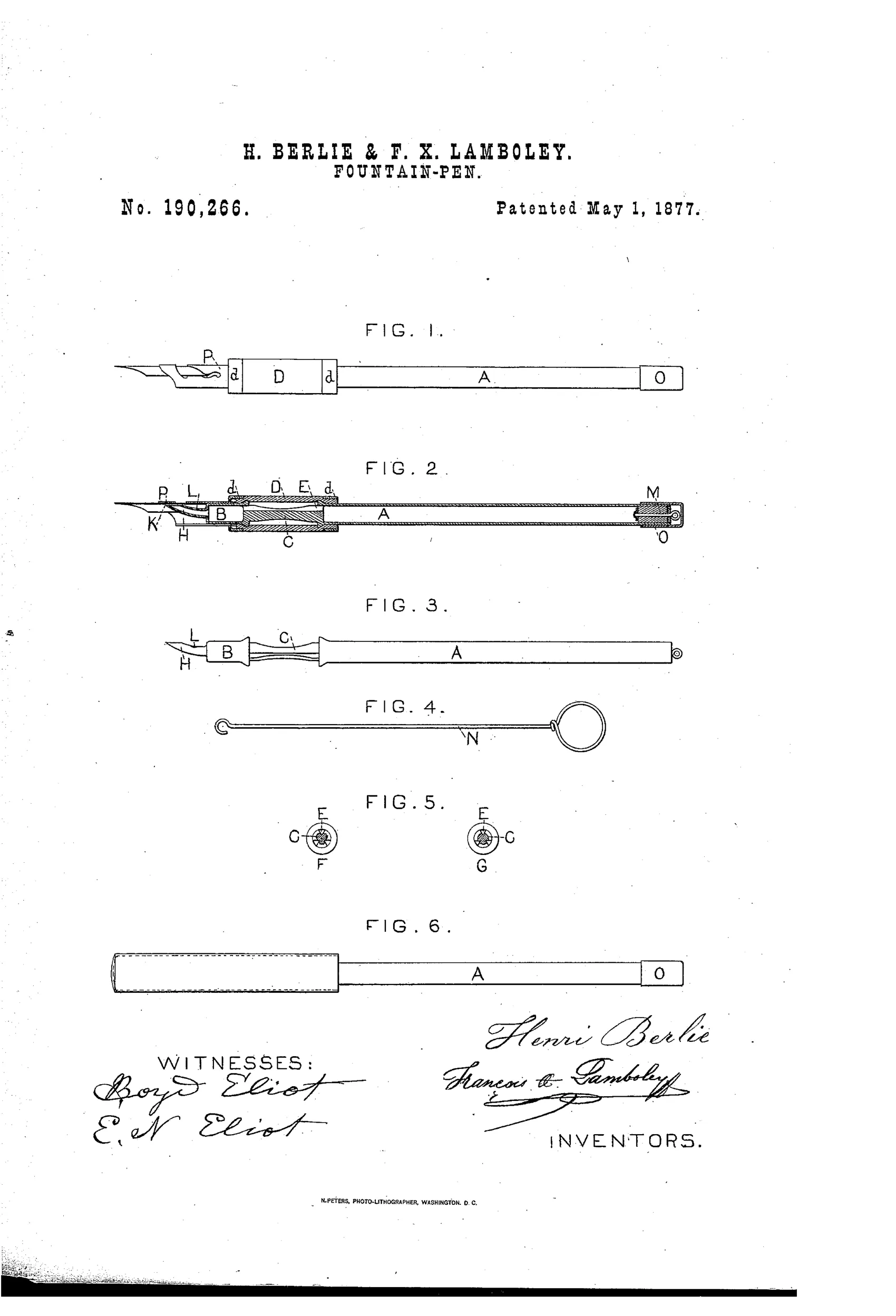
Fountain-pen holder with ink-flow control chamber
✒ How it works
The hollow stem A serves as an ink reservoir, connected via a solid rod C to a secondary elastic chamber B that surrounds the rod within an elastic tube D. Finger pressure on the elastic chamber D forces ink from chamber B through a curved tube H to the pen point K, while a vent hole L admits air to prevent excessive suck-back when pressure is released. Grooves or holes in rod C (shown in Fig. 5 as triangular or circular sections) allow ink to flow from the reservoir A into chamber B, and a plunger M at the far end of the reservoir acts as both a stopper and a piston for drawing ink into the holder via a hooked wire N. A removable cap O covers the plunger end, and may contain a rubber ink-eraser.
✒ What was claimed
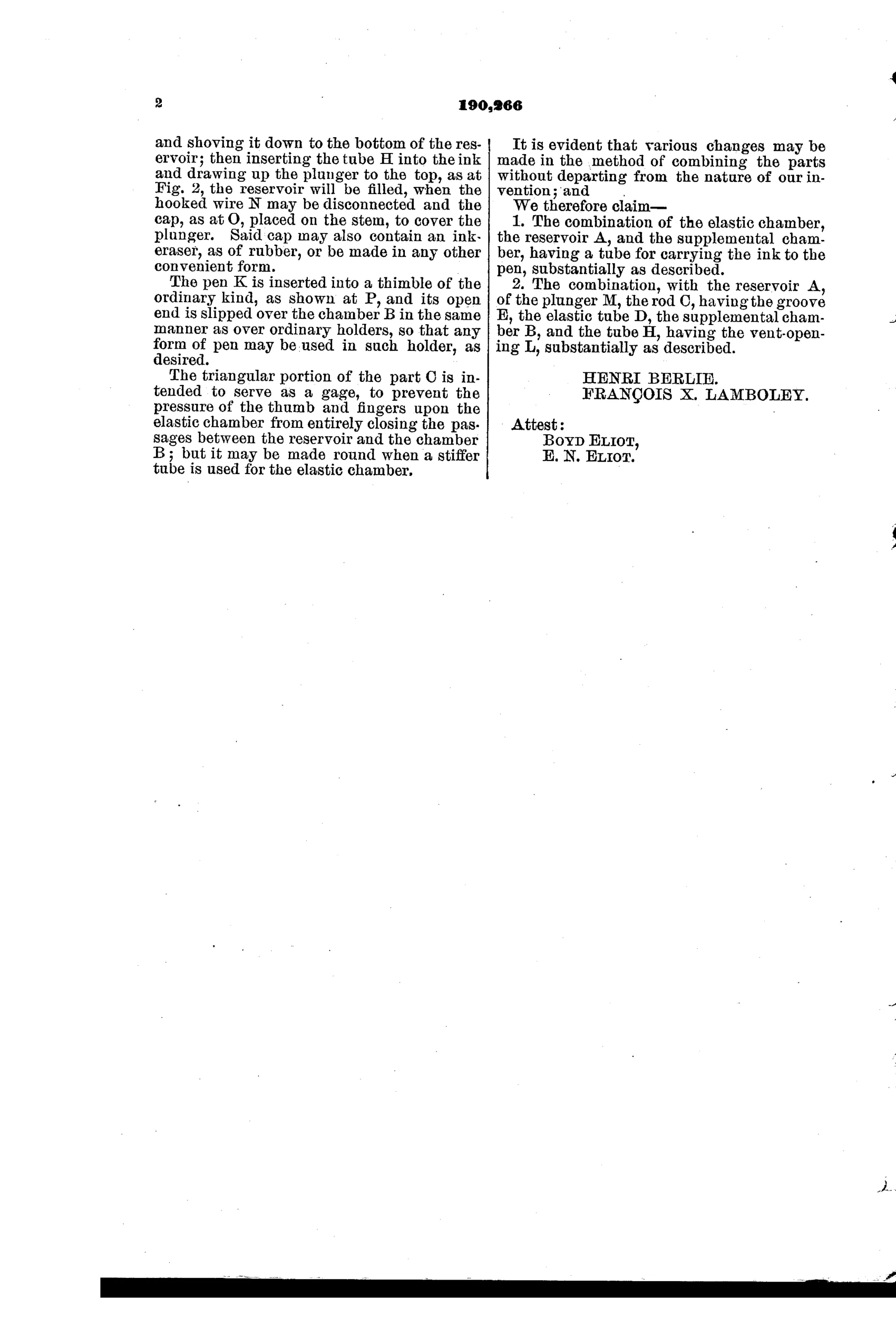
“The combination, with the reservoir A, of the plunger M, the rod C, having the groove E, the elastic tube D, the supplemental chamber B, and the tube H, having the vent-opening L, substantially as described.”
In plain English: The invention claims the combination of an ink reservoir with a plunger, a grooved connecting rod, a surrounding elastic tube, a secondary ink chamber, and a delivery tube with a vent hole, all working together as described.
✒ In the inventor’s words
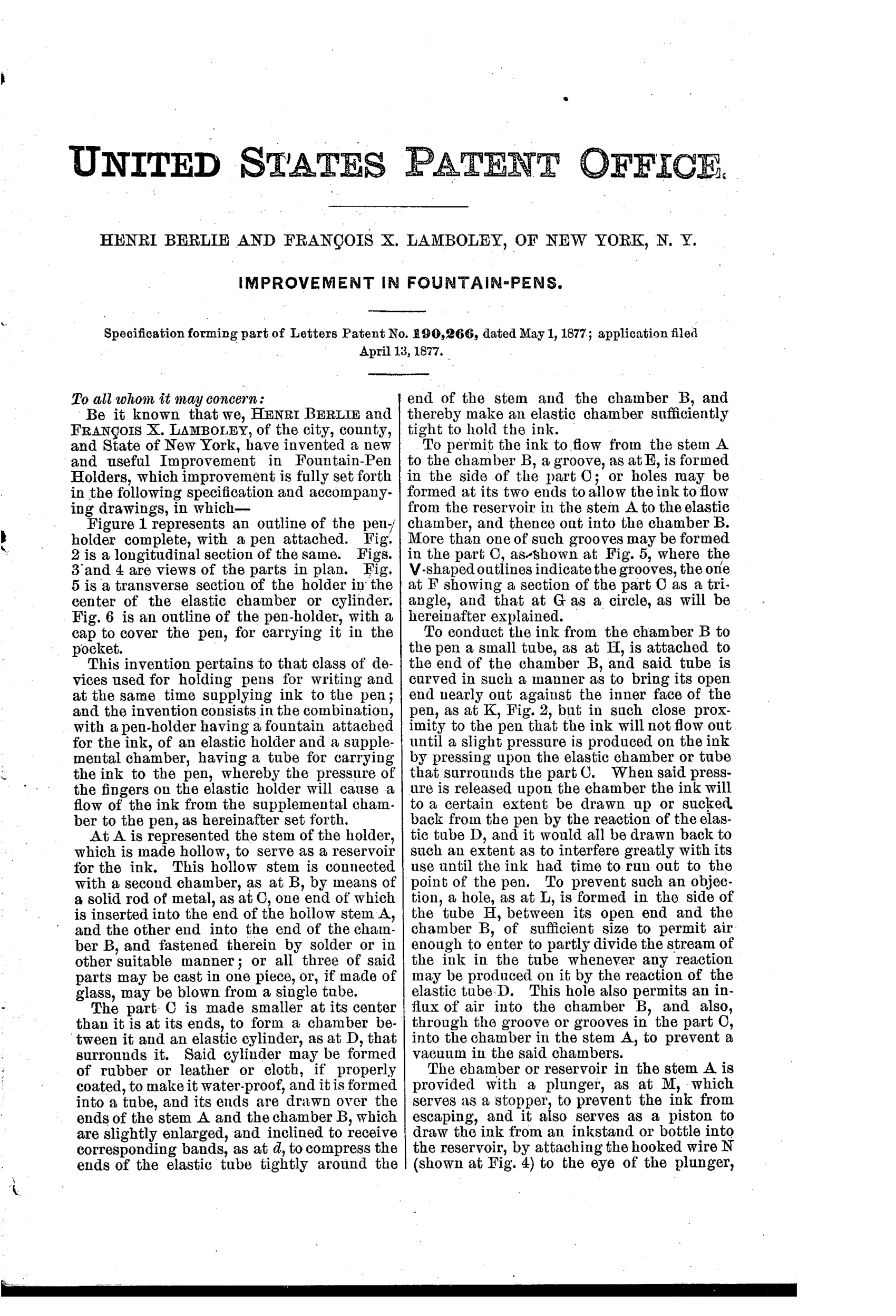
“When said pressure is released upon the chamber the ink will to a certain extent be drawn up or sucked back from the pen by the reaction of the elastic tube D, and it would all be drawn back to such an extent as to interfere greatly with its use until the ink had time to run out to the point of the pen.”— Henri Berlie and François X. Lamboley, from the specification
Fate unknown
No maker or marked example is documented for this design; a surviving specimen with the May 1, 1877 date would settle it.
✒ Patented the same day
- IMPROVEMENT IN FOUNTAIN-PENS — Alonzo T. Cross
✒ Commentary
This is a squeeze-to-write pen: you press the elastic tube D with your finger, ink is forced from the little supplemental chamber B down the curved tube H to the nib, and you write until the flow thins, then press again. That puts it squarely in the pre-Waterman stratum, where nobody yet trusted capillary action to meter ink and the writer was expected to do the pumping. As a daily instrument it would be tiresome — every squeeze risks a blob, and the flow depends entirely on the user's thumb discipline.
But read the best passage of the specification. Berlie and Lamboley observed that when you release the elastic chamber, its rebound sucks ink back up from the nib so strongly that the pen goes dry until ink creeps down again. Their fix is the tiny vent-opening L in the delivery tube: let air in, so the rebound draws air instead of ink. That is a genuine, correctly-diagnosed statement of the air-for-ink exchange problem — the very problem Waterman's 1884 feed solved elegantly with capillary channels. These two saw the disease clearly in 1877; they just patched the symptom.
There are other nice touches a casual reader misses: the grooved rod C (Fig. 5's triangular and round sections) metering ink into chamber B, the plunger M doubling as a piston filler worked by the hooked wire N, and a cap that hides a rubber eraser. Busy, earnest, and doomed — but the diagnosis was right.
Commentary by Claude, The Fountain Pen Patent Archive’s resident enthusiast