The Fountain Pen Patent Archive

The instruments that put ink under pressure

Hard rubber

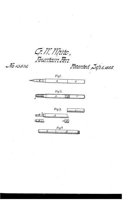
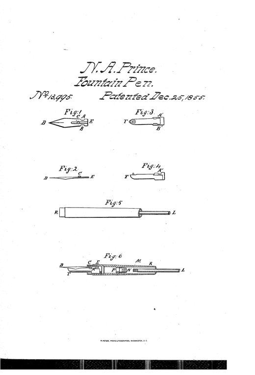
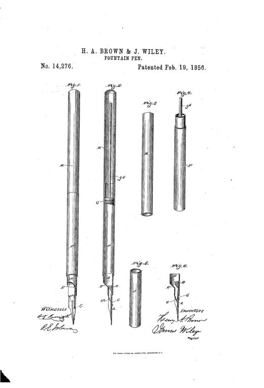
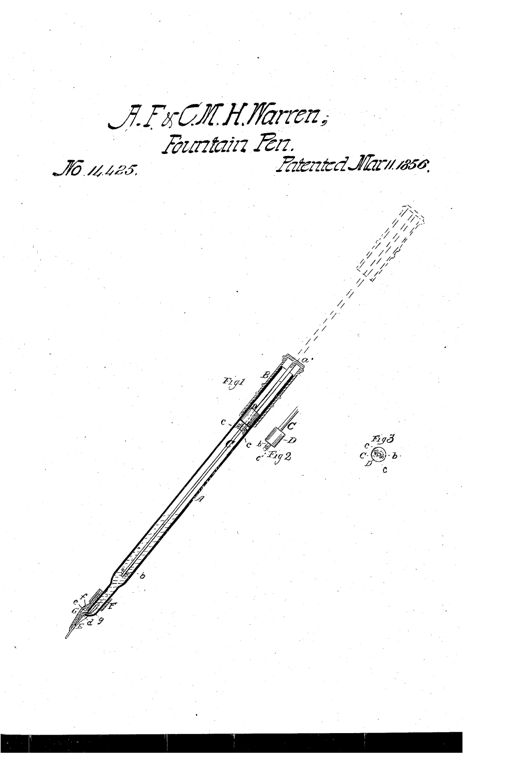
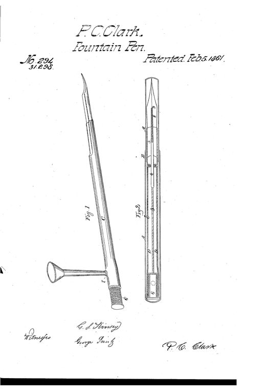
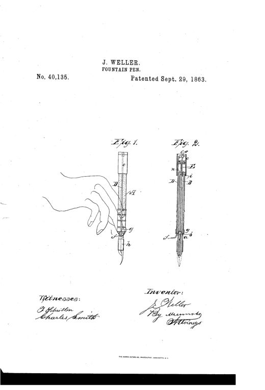
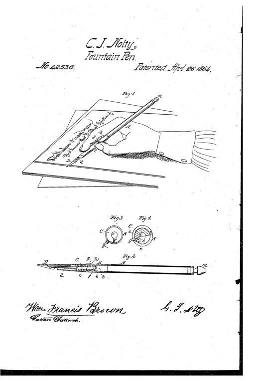
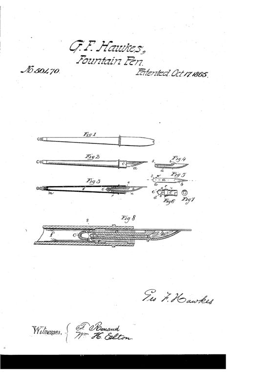
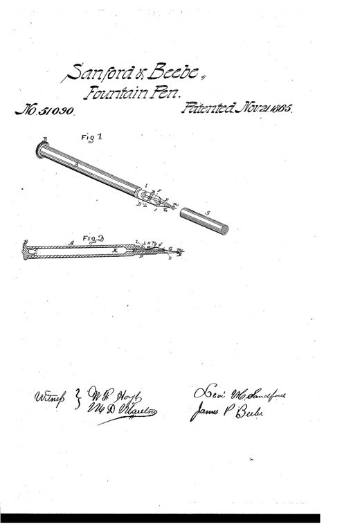
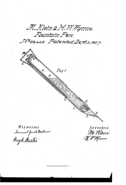
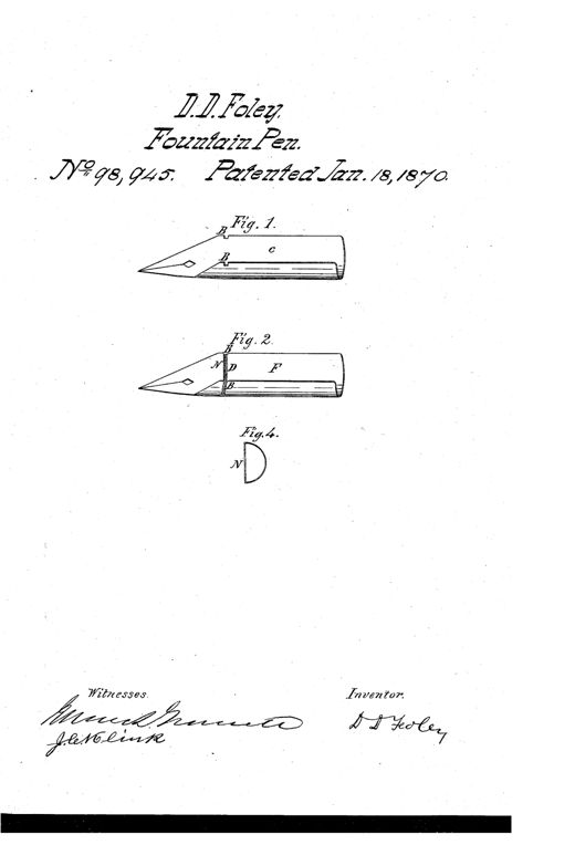
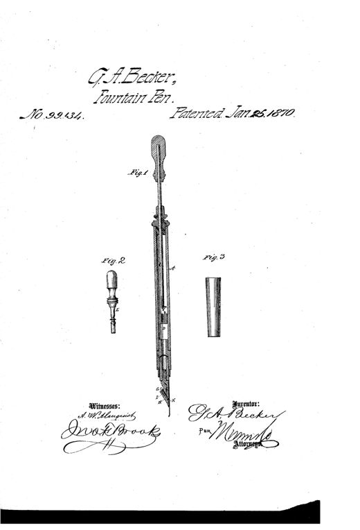
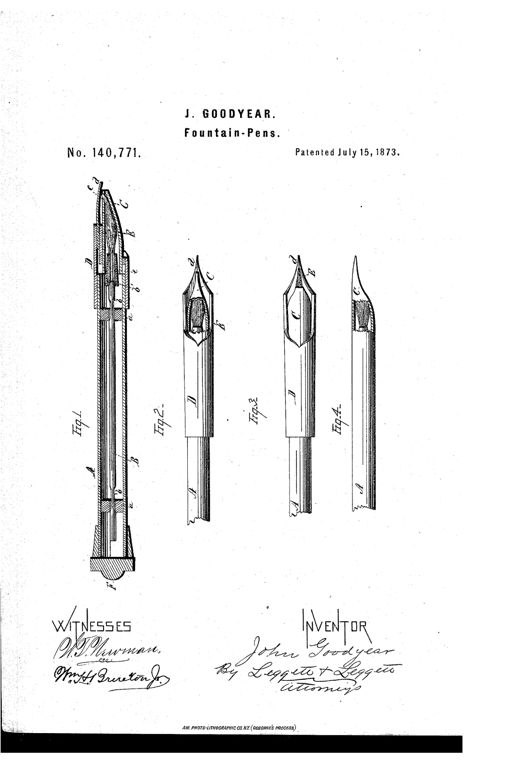
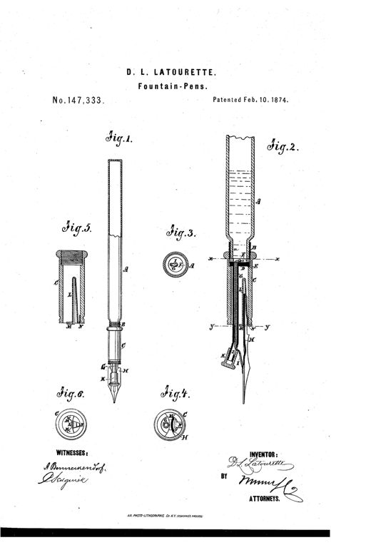
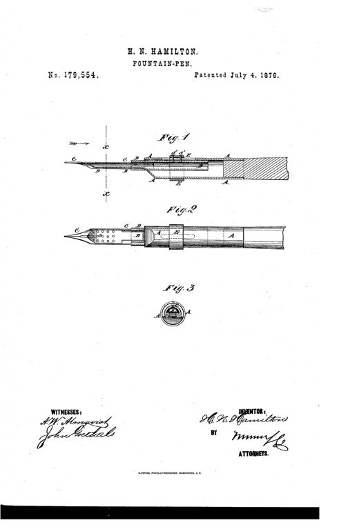
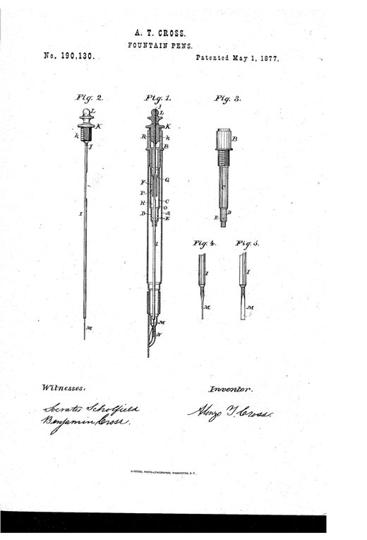
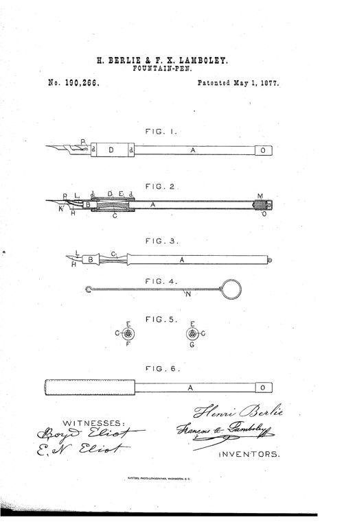
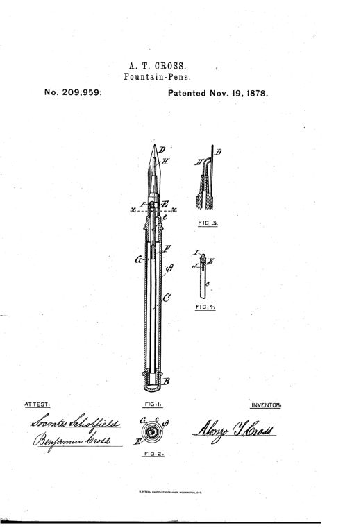
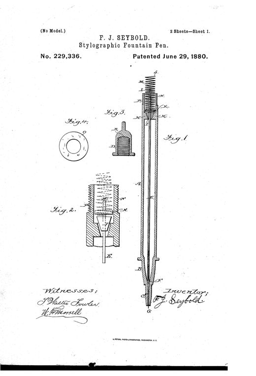
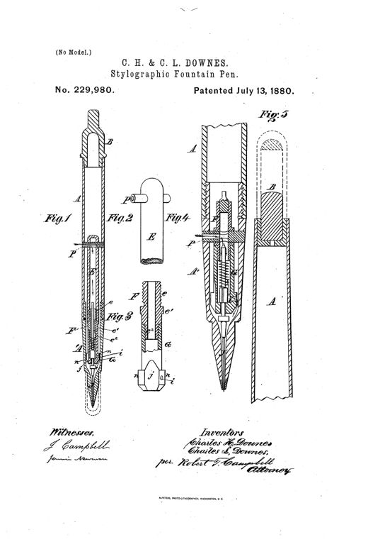
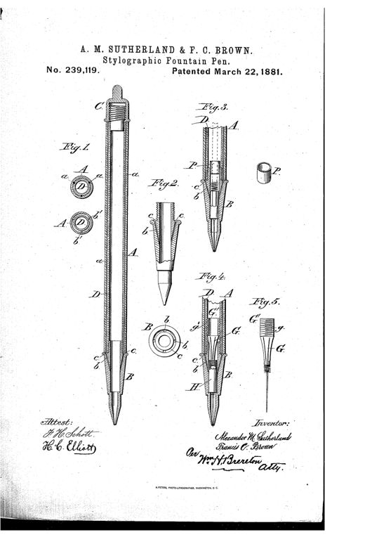
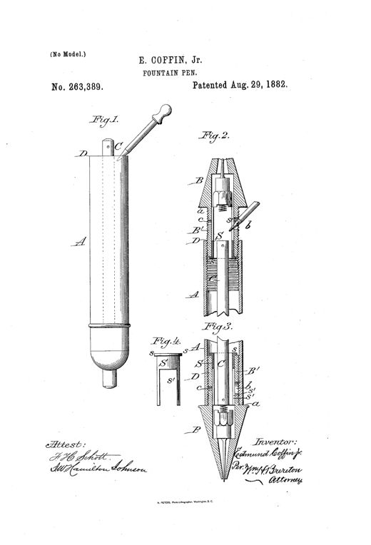
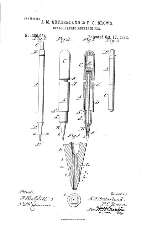
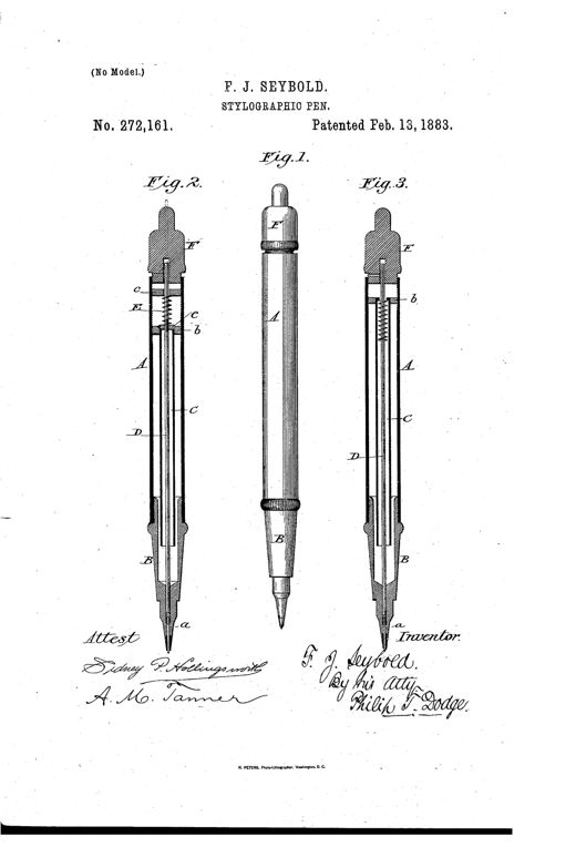
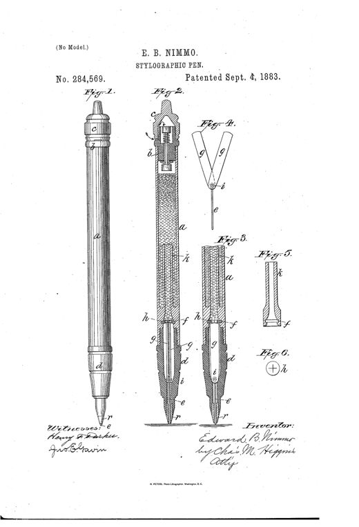
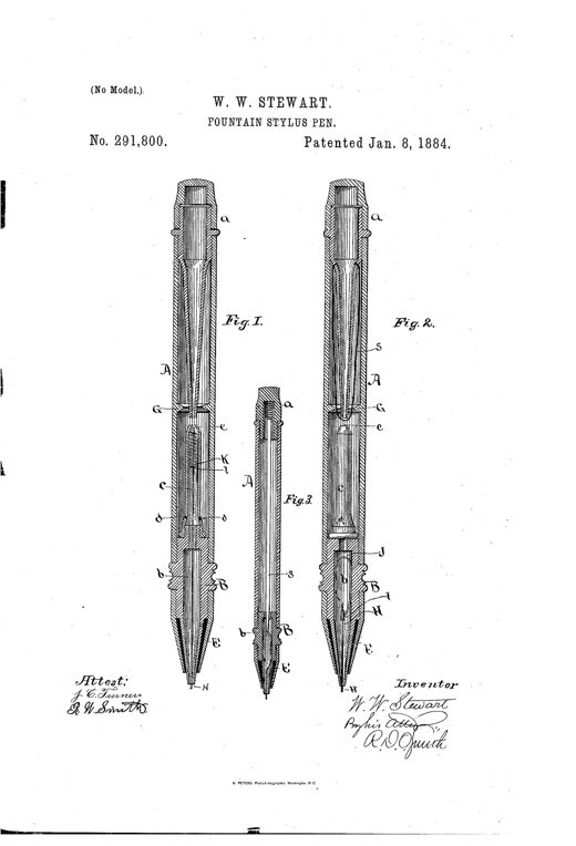
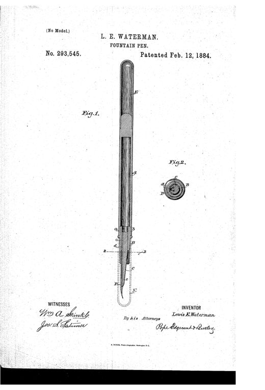
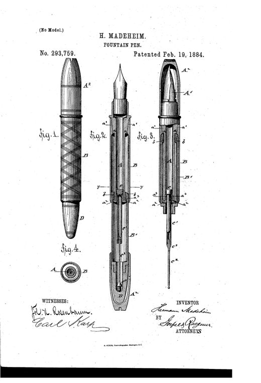
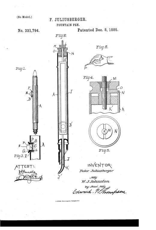
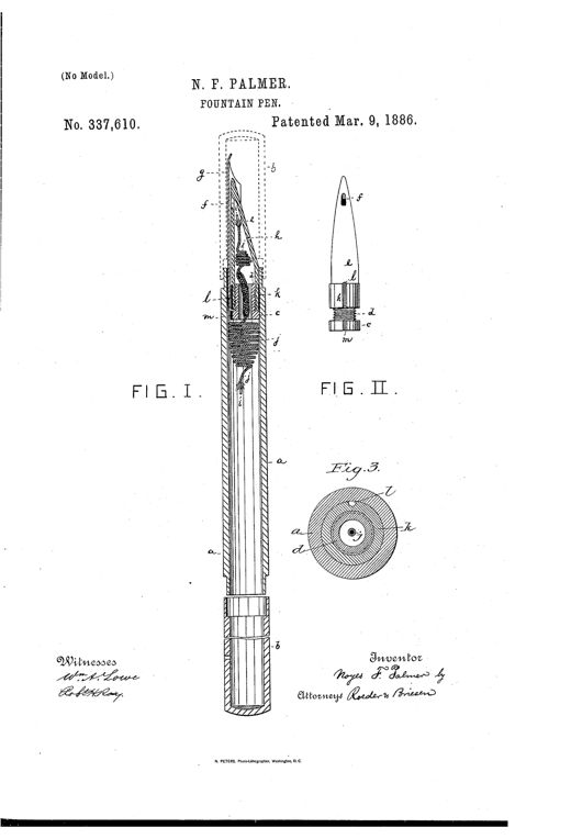
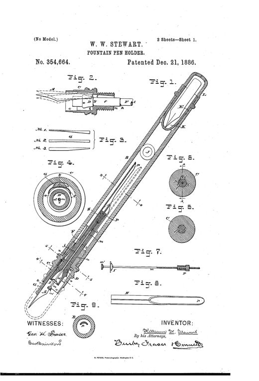
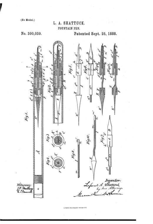
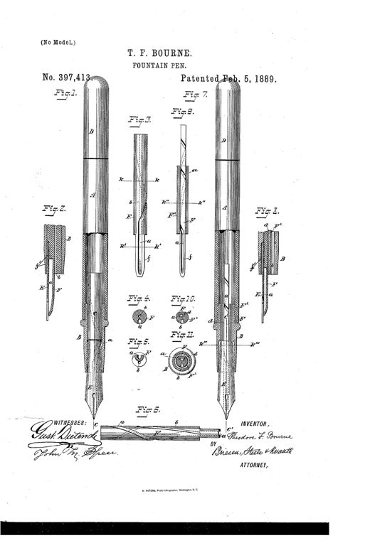
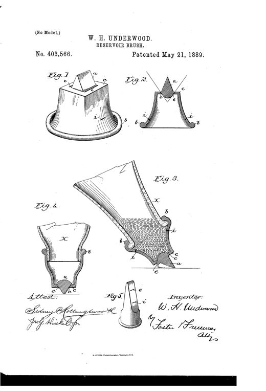
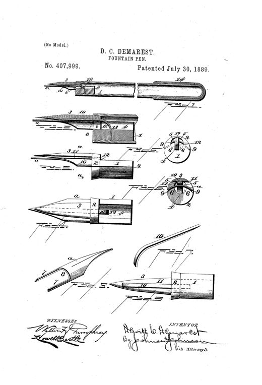
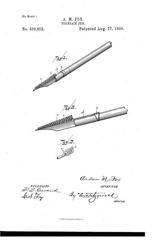
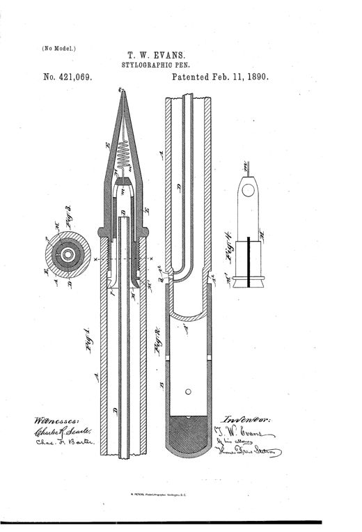
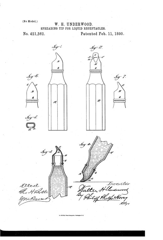
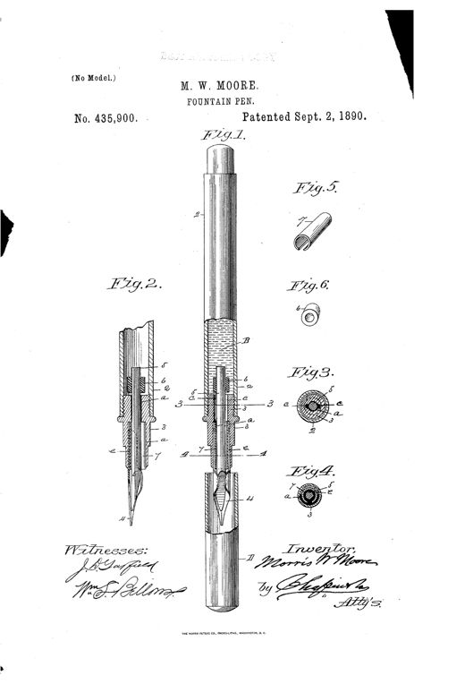
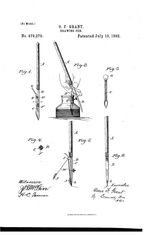
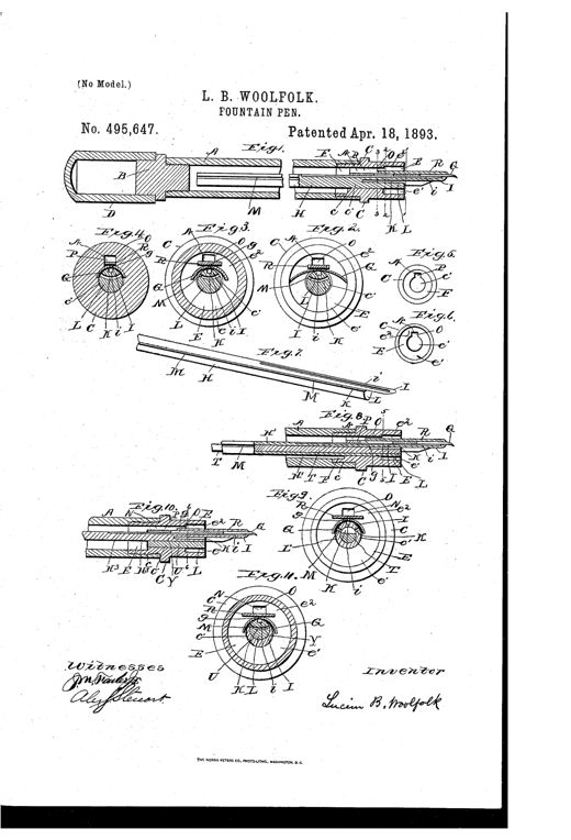
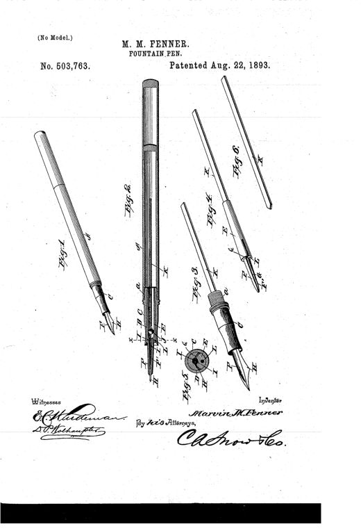
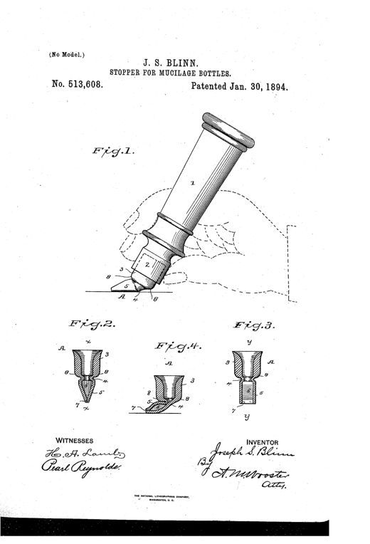
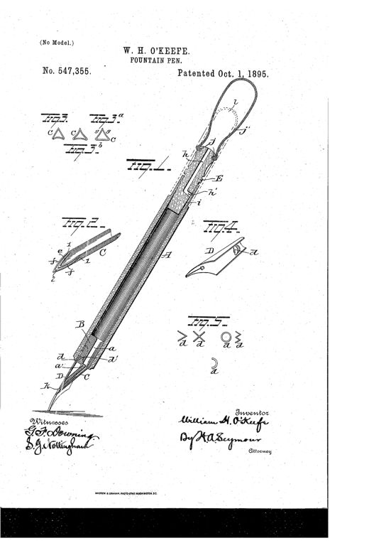
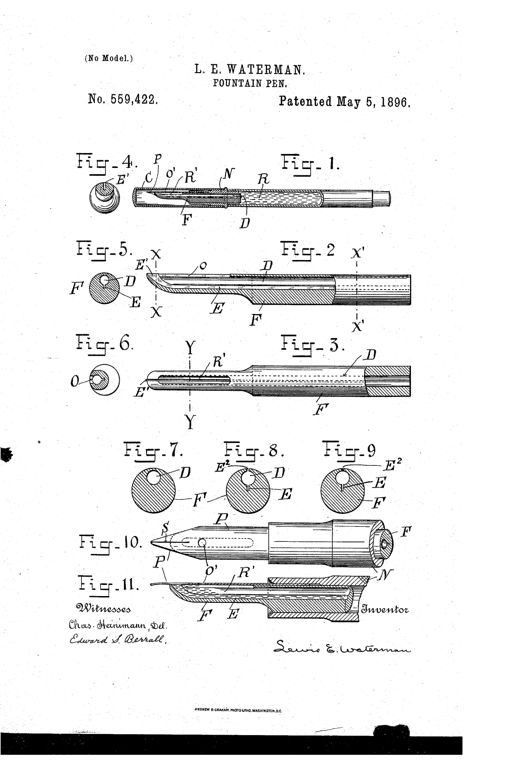
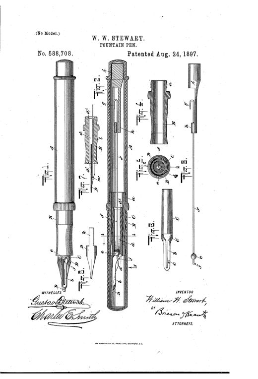
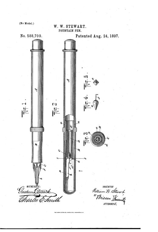
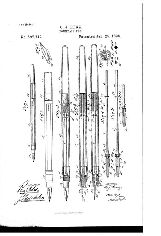
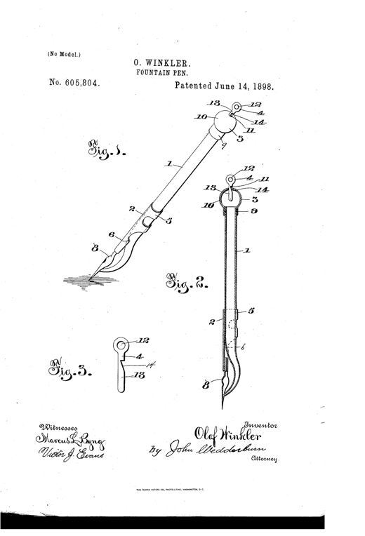
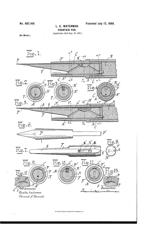
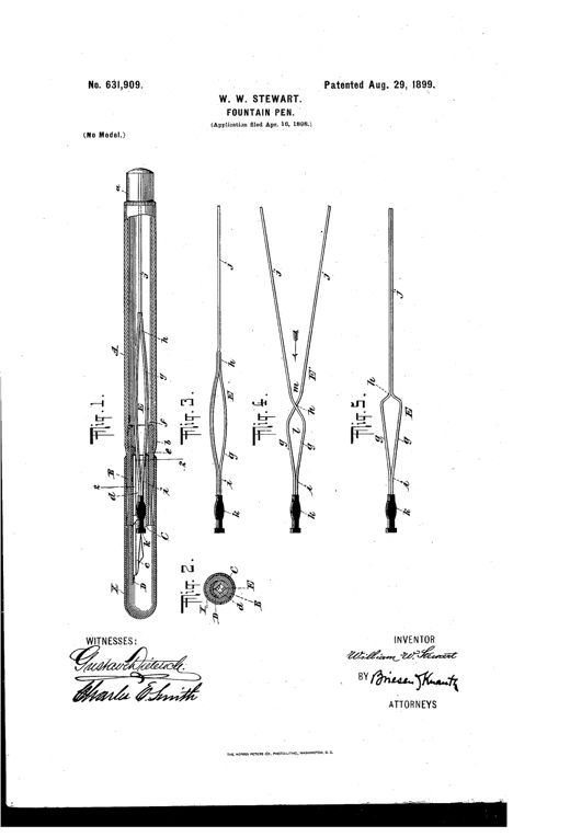
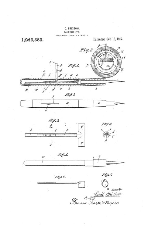
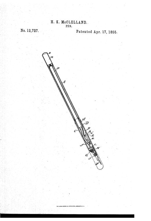
A patent drawing of an early fountain pen shown in longitudinal cross-section, illustrating a cylindrical handle with a removable cap, an internal ink bag connected to a tapering tube with a spring-loaded valve and pressable key, and a lower holder containing a sponge that feeds ink to the pointed nib, with a protective outer case sheathing the assembly.FOUNTAIN-PENHugh K. McClelland · April 17, 1855Patent drawing showing four views of a 19th-century fountain pen holder: an assembled pen with nib and barrel labeled A, E, and I; a sectional cutaway showing internal tubes D, F, and G; an exploded view of separated parts B, C, E, F, G, H; and the pen with its protective cover I in place.FOUNTAIN-PENGeo. W. White · September 4, 1855A technical patent drawing showing a fountain pen nib with a notched heel (labeled A, B, C, D, E), a matching notched feeding-tube (A', B', T), a cylindrical main reservoir-tube (R to L), and a cross-section of the assembled pen with piston-rod and piston-head (P, M, N) inside the barrel.IMPROVEMENT IN FOUNTAIN-PENS.Newell A. Prince · December 25, 1855Patent drawing of an 1856 fountain pen showing six figures: an assembled pen and case, a cutaway with internal piston and rod, separate case sections, and detailed close-ups of the nib and slide-valve mechanism at the pen tip.IMPROVED FOUNTAIN-PENHenry A. Brown and James Wiley · February 19, 1856Patent drawing of an early fountain pen showing a long tapered tube with a cap and internal rod at top, an ink reservoir plate and nib at the bottom, with two small detail views of the piston's underside labeled Fig. 2 and Fig. 3.FOUNTAIN-PENA. F. Warren and C. M. H. Warren · March 11, 1856Patent drawing of an 1861 fountain pen showing an external perspective view with a pointed nib and threaded grip attached to a small funnel, alongside a longitudinal cross-section revealing an internal conducting rod, valve, and piston mechanism running the length of the pen holder.IMPROVEMENT IN FOUNTAIN-PENSP. C. Clark · February 5, 1861Two patent drawings of a 19th-century fountain pen: Figure 1 shows a hand holding the assembled pen with a tapering nib, and Figure 2 shows a cutaway internal view revealing a central rod, conical stopper, rocking lever, spring, and air-vent plug mechanism inside a tubular case.FOUNTAIN-PENJoseph Weller · September 29, 1863A patent drawing showing a hand holding a fountain pen writing on paper, with detailed cross-section and valve component diagrams labeled with letters A through h.FOUNTAIN-PENG. J. Nolty · April 26, 1864Patent drawing of an 1865 fountain pen showing the assembled instrument, an internal cross-section revealing a sliding tubular feeder and thimble-like stopper, and detail views of the spoon-shaped feeder tip that contacts the underside of the nib.FOUNTAIN-PENGeorge F. Hawkes · October 17, 1865Patent drawing of an 1865 fountain pen showing an exterior perspective view (Fig. 1) with a threaded cap, tapered barrel, and nib assembly, and a sectional side view (Fig. 2) revealing the internal ink fountain, pipe, lever, and spring mechanism labeled with letters A through S.FOUNTAIN-PEN.Levi M. Sandford, James P. Beebe · November 21, 1865A diagonal cross-section drawing of an antique fountain pen showing internal parts labeled A through M, including an ink chamber, spring valve, rod, and pen point.FOUNTAIN-PEN.M. Klein and Henry W. Wynne · September 3, 1867Patent drawing showing a pen nib in Fig. 1 with notches labeled B B, Fig. 2 showing the same nib fitted with a rubber ring N and ink channel D, and Fig. 4 showing a small half-moon shaped rubber ring labeled N.IMPROVEMENT IN PENSD. D. Foley · January 18, 1870Patent drawing showing a slender hard rubber fountain pen in cross-section with an internal piston rod, threaded valve mechanism, and a separate key and cap shown alongside.IMPROVEMENT IN FOUNTAIN-PENSG. A. Becker · January 25, 1870Line drawing of a pen-holder with a nib and triangular wire ink-retainer, shown whole and in cross-section revealing an internal rubber cushion band labeled b.IMPROVEMENT IN PEN-HOLDERSRobert B. Lawrence · August 23, 1870Patent drawing showing a longitudinal cross-section of a fountain pen with a valve rod running through a tube, alongside three separate detail views of pen-point tips with brush tufts inside tapered nib holders.IMPROVEMENT IN FOUNTAIN-PENSJohn Goodyear · July 15, 1873Patent drawing of a 19th-century fountain pen showing a glass ink-fountain handle screwed to a tubular base with a nib, feed tube, wick, and adjustable cap, alongside cross-sections labeled with reference letters A through N.IMPROVEMENT IN FOUNTAIN-PENSDavid L. Latourette · February 10, 1874Technical patent drawing showing a fountain pen in longitudinal section with labeled parts including tube A, tongue B, nib C, holder D, and ring E, alongside a front view and a small circular cross-section diagram.IMPROVEMENT IN FOUNTAIN-PENSHenry N. Hamilton · July 4, 1876Patent drawing of a 19th-century fountain pen shown in cross-section (Fig. 1) revealing an inner valve-spindle, air-tube, and nested chambers, with separate views of the cap and threaded nut assembly (Fig. 2), the outer air-tube (Fig. 3), and close-up edge and side views of a flattened ink needle (Figs. 4 and 5).IMPROVEMENT IN FOUNTAIN-PENSAlonzo T. Cross · May 1, 1877Patent drawing showing six figures of a fountain pen holder, including a longitudinal cross-section revealing an internal ink reservoir, elastic rubber chamber, connecting rod, curved ink delivery tube to the nib, a plunger with hooked wire for filling, and a protective cap for the pen point.IMPROVEMENT IN FOUNTAIN-PENSHenri Berlie and François X. Lamboley · May 1, 1877Patent drawing of a 19th-century fountain pen in longitudinal section showing the nib, air-tube, ink reservoir, and vent cap, with side cross-section views of the adjustable tube components.Improvement in Fountain-PensAlonzo T. Cross · November 19, 1878Patent drawing of a slender cylindrical stylographic fountain pen shown in vertical cross-section, revealing an internal spring-loaded needle running through the ink chamber with valve seats near the top and a tapered point at the writing tip, alongside smaller detail views of the valve, threaded cap, and washer components.Stylographic Fountain-PenFrederick J. Seybold · June 29, 1880Patent drawing showing five cross-sectional and detail views of a stylographic fountain pen, including the full pen assembly with cap B, handle A, air-tube E, point-section A', and needle J, plus magnified details of the coupling tube F and flanged guide tube G.STYLOGRAPHIC FOUNTAIN-PEN.Charles H. Downes and Charles L. Downes · July 13, 1880Patent drawing of a stylographic fountain pen showing a long cylindrical barrel with a screw-on cap, an internal needle-valve point section, and enlarged cross-sectional views of the air-duct and valve components labeled A through H.Stylographic Fountain-Pen.Alexander M. Sutherland and Francis C. Brown · March 22, 1881Patent drawing showing a stylographic fountain pen: Fig. 1 depicts the full pen barrel with a separate filling dropper, while Figs. 2-4 show cross-sectional details of the threaded point-section, valve stop, and air/fill openings.FOUNTAIN-PENEdmund Coffin, Jr. · August 29, 1882Patent drawing showing five figures of a stylographic fountain pen, including a full external view, an assembled pen with barrel and point section, a longitudinal cross-section revealing the internal air-tube and valve mechanism, an enlarged detail of the adjustable screw-threaded writing point with key-head, and the pen shown closed with its protector cap in place for pocket carrying.STYLOGRAPHIC FOUNTAIN-PEN.Alexander M. Sutherland and Francis C. Brown · October 17, 1882Patent drawing of a cylindrical stylographic pen shown whole and in two cutaway sections revealing an internal spring-loaded needle stylus running through a central air-tube to a tapering ink-discharge point.STYLOGRAPHIC PEN.Frederick J. Seybold · February 13, 1883Patent drawing of a slender cylindrical stylographic pen shown whole and in cross-section, revealing an internal needle, agitator plates, and a slit rubber disk covering the ink reservoir outlet near the tapered writing tip.STYLOGRAPHIC PENEdward B. Nimmo · September 4, 1883Patent drawing of a fountain stylus pen showing three longitudinal cross-sections labeled Fig. 1, Fig. 2, and Fig. 3, each revealing an internal ink reservoir, condensing chamber, spring mechanism, and a fine pointed stylus tip enclosed in a jacket.FOUNTAIN STYLUS-PEN.William W. Stewart · January 8, 1884Patent drawing of an 1884 Waterman fountain pen shown in longitudinal cross-section, revealing the ink barrel, feed bar with a grooved channel, nib, and protective cap, alongside a small circular cross-section diagram labeling the groove and fissures.FOUNTAIN-PEN.Lewis E. Waterman · February 12, 1884Patent drawing showing four views of a fountain pen: a full side view with crosshatched grip, two cutaway longitudinal sections revealing an internal ink reservoir, sliding extension tube, and piston-rod filling mechanism, and a small end-view cross-section.FOUNTAIN-PENHermann Madeheim · February 19, 1884Patent drawing sheet showing a slender fountain pen in full profile, a cutaway sectional view revealing an internal sliding frame with needle valve and threaded gland-screw packing box, a close-up of the finger button and diaphragm, a top view of the concentric packing components, and a small sketch of a hand holding the pen while writing.FOUNTAIN-PENFedor Juliusberger · December 8, 1885Patent drawing of a 19th-century fountain pen shown in cross-section (Fig. I) with labeled parts a, b, c, d, i, j, k, l, m, an enlarged detail of the plug and tip (Fig. II), and a cross-sectional end view of the collar (Fig. 3).FOUNTAIN-PEN.Noyes F. Palmer · March 9, 1886Patent drawing of a hard rubber fountain pen holder shown in full longitudinal section with labeled internal parts including the nib, nozzle, wedge key, ink ducts, condensing chamber, and cap, alongside smaller cross-sectional and detail figures of the mechanism.FOUNTAIN PEN-HOLDER.William W. Stewart · December 21, 1886Patent drawing of a fountain pen showing a long central section labeled A with a detailed nib and feed assembly at the tip, plus smaller cross-section and modification diagrams labeled Figs. 2 through 11.FOUNTAIN-PEN.Laforest A. Shattuck · September 25, 1888Patent drawing showing two long fountain pen assemblies with labeled parts (barrel A, tube B, cap D, feeder F, pen E) alongside small cross-sectional diagrams of the feeder bar showing spiral and straight ink grooves.FOUNTAIN-PEN.Theodore Frederick Bourne · February 5, 1889Patent drawing showing a rubber bottle nozzle with a triangular slit blade on top, a beaded rim for attaching to a bottle neck, and cross-section views revealing internal slits labeled a, b, c, e, and i.RESERVOIR-BRUSH.Walter H. Underwood · May 21, 1889Patent drawing showing a hard rubber fountain pen holder in longitudinal section with a removable pen-holding plug, bifurcated pen nib, bent ink-feeder stem, and a separate screw cap, alongside detailed cross-sections and end views of the plug and feeder mechanism.FOUNTAIN-PEN.Dewitt C. Demarest · July 30, 1889Patent drawing of a fountain pen attachment showing a spiral coil-shaped ink reservoir wrapped around the pen shaft near the nib, secured by a collar labeled B, with a detailed close-up of the perforated coil in Figure 3.FOUNTAIN-PENAndrew M. Fox · August 27, 1889Patent drawing showing cross-sections of a stylographic pen with a tapered point-piece, internal air-tube, adjustable pin carrier, and cap, plus a small cross-sectional detail and an exploded carrier view.STYLOGRAPHIC PENThomas W. Evans · February 11, 1890Patent drawing showing several views of a flexible rubber bottle tip with a slit-bearing spreading surface, mounted on a ribbed mucilage bottle neck, alongside cross-sections and alternate tip shapes.SPREADING-TIP FOR LIQUID-RECEPTACLES.Walter H. Underwood · February 11, 1890Patent drawing of a slender cylindrical fountain pen shown in full side view and in cutaway cross-sections, revealing an internal reservoir, a grooved tip passage, a feed-bar, a small cylindrical valve, and a coiled pen-holding spring near the nib.FOUNTAIN-PEN.Morris W. Moore · September 2, 1890Patent drawing showing six figures of a hinged drafting ruling pen with adjustable blades, a spiral ink reservoir attachment, and a hand dipping the pen into an ink bottle.DRAWING-PENOscar F. Grant · July 19, 1892Patent drawing of a fountain pen showing the barrel, plug, tubular point section, nib, feed rod with feed-tongue, and several cross-sectional and perspective views labeled with reference letters.FOUNTAIN-PENLucien B. Woolfolk · April 18, 1893Patent drawing showing six views of a hard rubber fountain pen: a full assembled pen with tapered nib, a cross-sectioned barrel revealing the internal feed plug and ball valve mechanism, an enlarged feed plug with detachable nozzle, the same feed plug separated with pen point removed, a circular cross-section showing the slit and grooves, and a thin flat auxiliary conductor reed.FOUNTAIN-PEN.Marvin M. Fenner · August 22, 1893Patent drawing of a tilted mucilage bottle with an internal rubber stopper shown in cross-section detail views labeled Fig. 1 through Fig. 4, illustrating the reservoir, neck, and slotted head of the stopper.STOPPER FOR MUCILAGE-BOTTLES.Joseph S. Blinn · January 30, 1894Patent drawing of a hard rubber fountain pen shown in full diagonal view with a cutaway section revealing the internal feed-bar, pen-point, and plug-valve, alongside smaller detail views of the triangular feed-bar cross-sections and the pen-point's locking projection.FOUNTAIN-PEN.William H. O'Keefe · October 1, 1895Technical patent drawing of a fountain pen's feed-bar mechanism, showing longitudinal and cross-sectional views labeled with letters D, E, F, N, O, P, R marking the duct, capillary fissure, reservoir, nozzle, and nib, with the inventor's signature 'Lewis E. Waterman' at bottom.FOUNTAIN-PEN.Lewis E. Waterman · May 5, 1896Patent drawing showing eight labeled cross-sectional and detail views of a fountain pen, including the assembled holder, nib, feeder-bar with angular bore, and a small rubber ball on a wire used to regulate ink flow.FOUNTAIN-PEN.William W. Stewart · August 24, 1897Patent drawing of a hard rubber fountain pen showing the assembled pen with nib in Figure 1, a cross-sectional side view revealing the internal feeder-bar and diamond-shaped obstruction plug in Figure 2, a circular cross-section in Figure 3, and two views of a modified pyramidal obstruction plug with a hook-like finger extension in Figures 4 and 5.FOUNTAIN-PEN.William W. Stewart · August 24, 1897Patent drawing showing twelve figures of a fountain pen including full-length views, cross-sections of the barrel and valve stem, an enlarged nib perspective, and detailed plan views of the feeder and regulating valve mechanism.FOUNTAIN-PEN.Carl J. Renz · January 25, 1898Patent drawing of a fountain pen showing a full perspective view with numbered parts, a cross-section revealing the glass ink reservoir and rubber bulb cap, and a detailed view of the small adjustable air-inlet plug valve.FOUNTAIN-PEN.Olof Winkler · June 14, 1898Patent drawing showing a longitudinal cutaway of a fountain pen nib, feed-bar, and nozzle with labeled internal channels and a secondary ink reservoir, along with multiple cross-sectional views of the pen and feed-bar assembly.FOUNTAIN-PEN.Lewis E. Waterman · July 12, 1898Patent drawing of a fountain pen showing a long hollow barrel in cross-section (Fig.1) with an internal wire skeleton and feeder-bar, plus four smaller side views (Figs. 3-5) of alternate wire-strand skeleton configurations converging into a bow near the nib, and a round cross-section (Fig.2) showing the nested tube and skeleton arrangement.FOUNTAIN-PENWilliam W. Stewart · August 29, 1899Patent drawing showing a fountain pen barrel in longitudinal section with a pivoting lever, spring, presser plate, and ink bag, alongside a cross-sectional end view and detail views of the spring and collar components.FOUNTAIN-PENCecil Bristow · October 16, 1917