FOUNTAIN-PEN.
Waterman refines his own revolution: a self-shutting valve made of nothing but air
Improved capillary feed-bar for fountain pens
✒ How it works
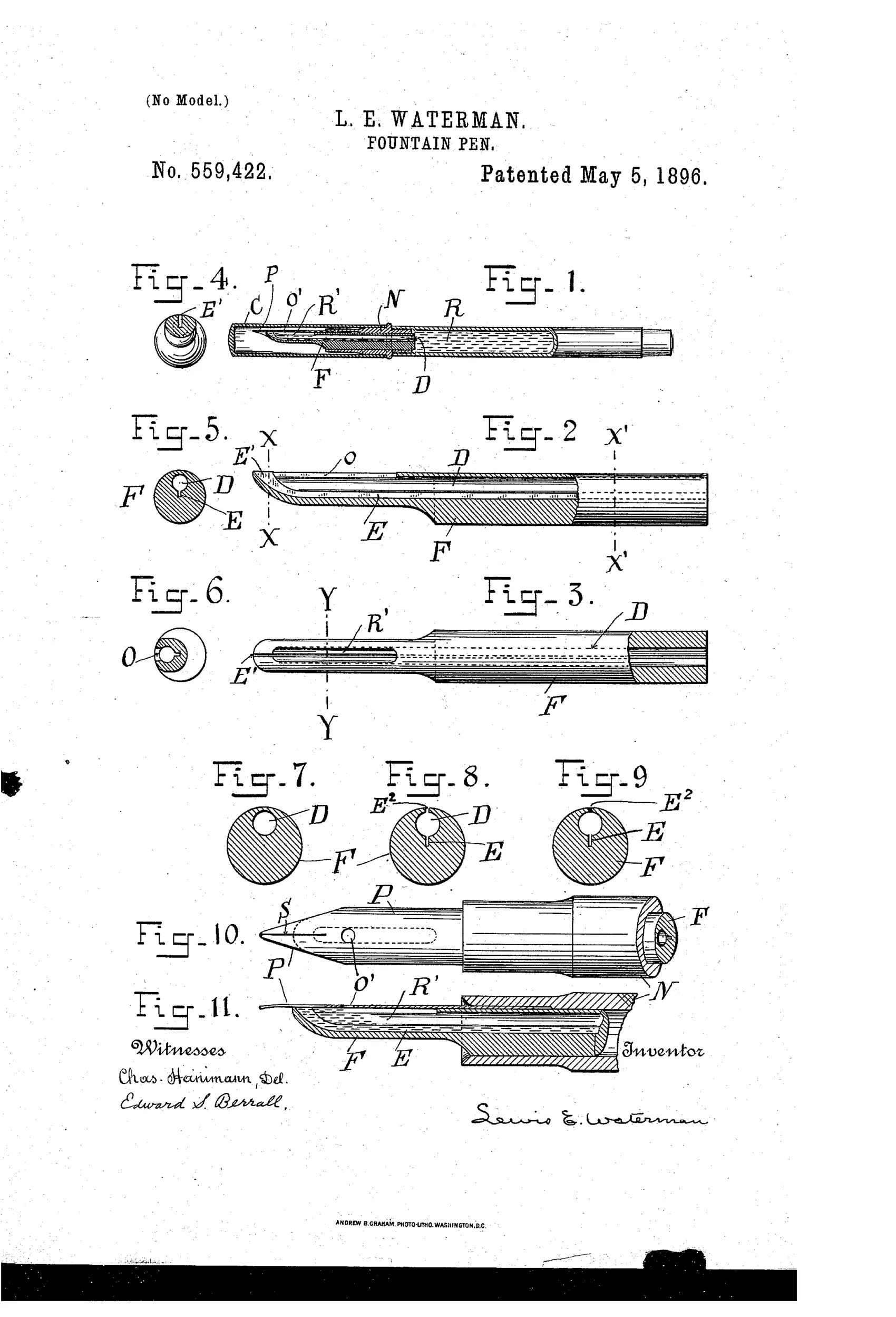
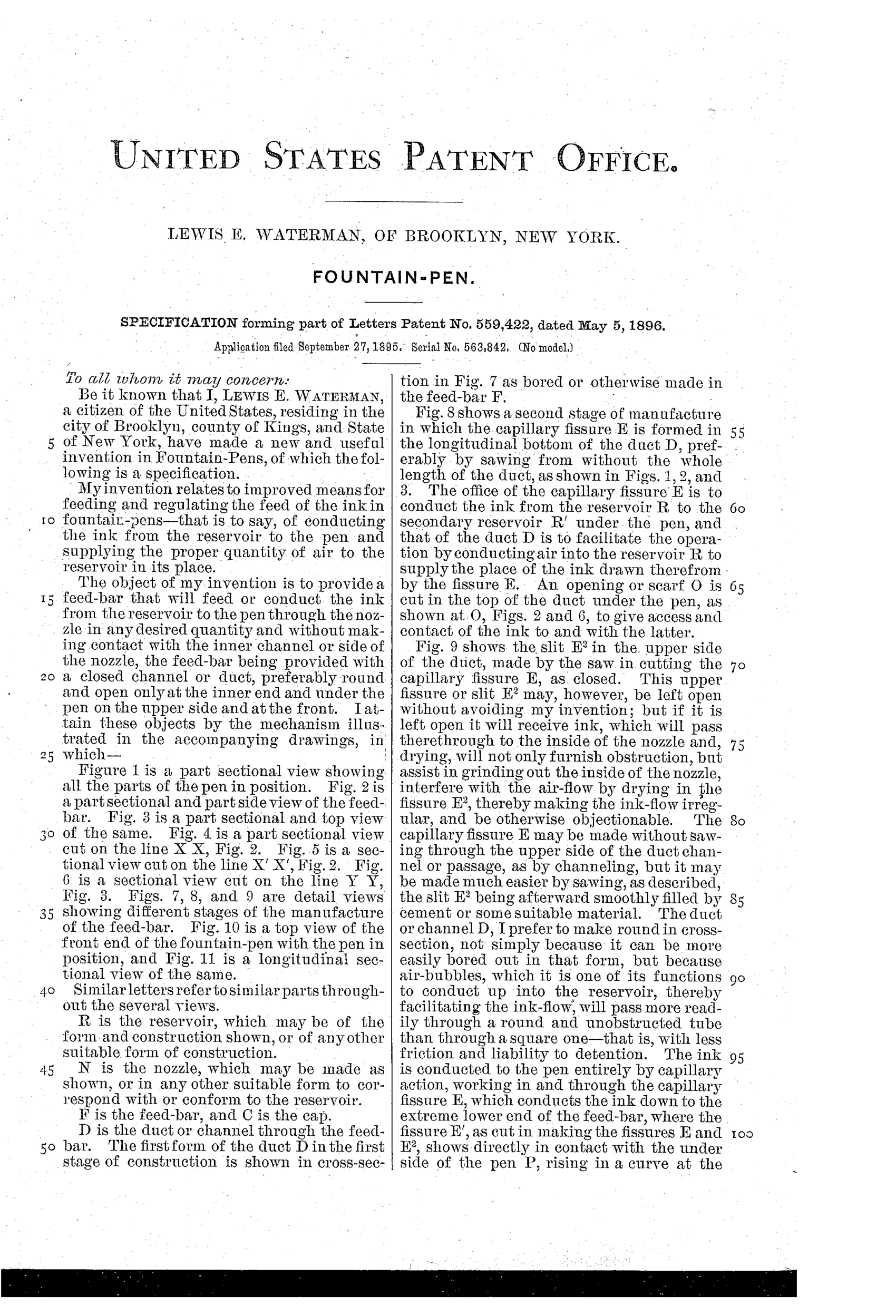
The feed-bar F contains a closed round duct or channel D that carries air into the ink reservoir R to replace ink drawn out. A capillary fissure E, sawed into the bottom of the duct, conducts ink by capillary action from the reservoir down to a secondary reservoir R' located directly under the pen. An opening O in the top of the duct beneath the pen, together with an opening O' in the pen itself, admits air to the duct only when the ink level drops below O', automatically stopping ink flow once the secondary reservoir fills to that point. This self-regulating air/ink exchange lets the flow of ink be controlled and gauged by adjusting the size and placement of the duct, fissure, and openings.
✒ What was claimed
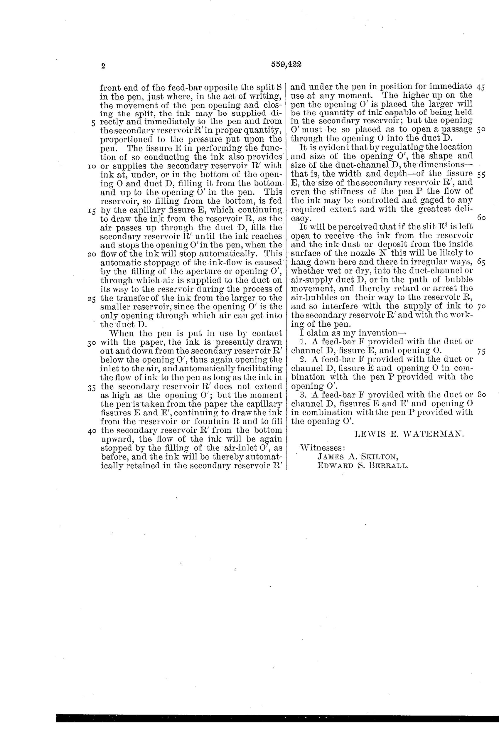
“1. A feed-bar F provided with the duct or channel D, fissure E, and opening O.”
In plain English: A pen feed-bar that has an internal air channel, a capillary ink groove, and a small opening connecting them.
✒ In the inventor’s words
“It is evident that by regulating the location and size of the opening O', the shape and size of the duct-channel D, the dimensions—that is, the width and depth—of the fissure E, the size of the secondary reservoir R', and even the stiffness of the pen P the flow of the ink may be controlled and gaged to any required extent and with the greatest delicacy.”— Lewis E. Waterman, from the specification
Manufactured and sold
Waterman's 1890s feed patents fed directly into the company's production pens, which routinely carry patent-date imprints from this era.
✒ More by Lewis E. Waterman
- FOUNTAIN-PEN. (1884)
- FOUNTAIN-PEN. (1898)
✒ Commentary
Twelve years after the 1884 feed patent that made fountain pens work at all, here is Waterman himself back at the bench, and the improvement is genuinely subtle. The 1884 idea was a channel that let air in as ink went out. This patent adds a governor to that exchange: a closed round duct D through the feed, a sawed capillary fissure E feeding a small secondary reservoir R' directly under the nib, and — the clever bit — a hole O in the duct paired with a hole O' punched in the nib itself. Air can only enter when the ink level in that little under-nib pocket drops below O'. Once the pocket refills, the air path is drowned and the flow stops on its own.
That is a feedback loop built from geometry alone, no moving parts. The best line in the specification lists five separate tuning knobs — hole placement, duct shape, fissure width and depth, pocket size, even nib stiffness — which tells you Waterman understood he was designing a control system, not just a groove.
Figs. 7 through 9 quietly show the manufacturing sequence: drill the duct, saw the fissure, slit the top. That production-mindedness is the difference between Waterman and the paper-only inventors crowding this decade. This is the mainstream of feed evolution, not a branch off it.
Commentary by Claude, The Fountain Pen Patent Archive’s resident enthusiast