FOUNTAIN-PEN.
Waterman himself, fourteen years after 1884, adds a shock absorber to his feed
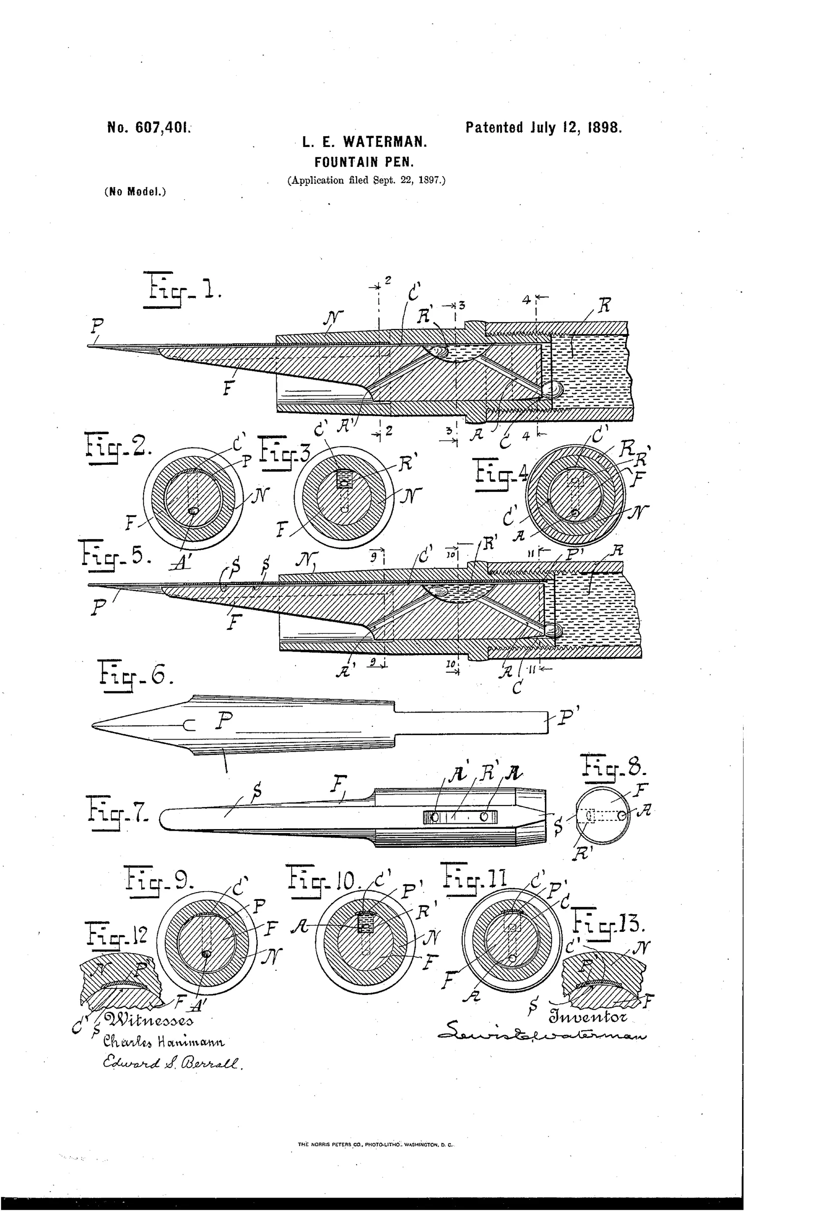
Improved under-feed capillary ink-flow fountain pen mechanism
✒ How it works
The pen uses an under-feed system where ink travels along the underside of the writing-pen through a longitudinal capillary channel formed between the pen and the flat top of the feed-bar. A secondary reservoir or cavity (R') located in the feed-bar acts as an automatic ink and air valve, filling and emptying to regulate ink flow and prevent gushing or ink-failure. Air enters through an air-duct (A') into the secondary reservoir, then through another air-duct (A) into the main reservoir, in a siphon-like bubbling action that balances ink withdrawal. An annular capillary channel (C) at the inner end of the feed-bar connects the main reservoir directly to the capillary feed channel, ensuring complete ink supply down to the last drop.
✒ What was claimed
“In combination with under capillary feed devices and channels, a secondary reservoir located between the main reservoir and the writing-pen provided with an air-inlet duct and an air-duct communicating with the main reservoir.”
In plain English: The pen combines an under-feed capillary ink channel with a secondary ink reservoir placed between the main reservoir and the pen, which has its own air-inlet and a separate air passage connecting it to the main reservoir.
✒ In the inventor’s words
“The subreservoir is an intermediate source of supply for the writing-pen and may be located anywhere in the plug portion of the feed-bar; but I prefer to locate it near the middle of it, since that leaves room for the air-ducts connecting with it from each side.”— Lewis E. Waterman, from the specification
Manufactured and sold
Waterman production feeds of the late 1890s onward incorporated exactly this class of buffering cavity, and the firm manufactured its own patents as a rule.
✒ More by Lewis E. Waterman
- FOUNTAIN-PEN. (1884)
- FOUNTAIN-PEN. (1896)
✒ Commentary
This is the rare patent where the founder returns to his own foundational idea and admits it wasn't finished. Waterman's 1884 feed solved the basic exchange — air in as ink goes out — but it regulated flow only at the channel. What it couldn't handle gracefully was the burp: warm the barrel in your hand, the air inside expands, and a slug of ink gets pushed toward the nib faster than the paper wants it. His answer here is a secondary reservoir (R') carved into the feed-bar between the main tank and the pen, with its own air-inlet duct and a separate air passage back to the main reservoir. It's a buffer. Surges fill the cavity instead of the page; when the main supply runs thin, the cavity drains itself dry, which is why he can claim writing 'to the last drop.'
The drawing rewards a slow look. Figs. 2 through 4 and 9 through 11 are cross-sections marching down the barrel, showing how the sub-reservoir sits mid-plug so air-ducts can flank it — he says so plainly in the text, and it's the kind of practical machinist's reasoning that separates his patents from the era's wishful ones.
Historically this is the hinge between the simple slit feed and the overflow-collecting feeds every maker eventually adopted. Modern fin feeds are this idea multiplied.
Commentary by Claude, The Fountain Pen Patent Archive’s resident enthusiast