IMPROVEMENT IN FOUNTAIN-PENS
A camel's-hair brush as ink feed, eleven years before Waterman solved it
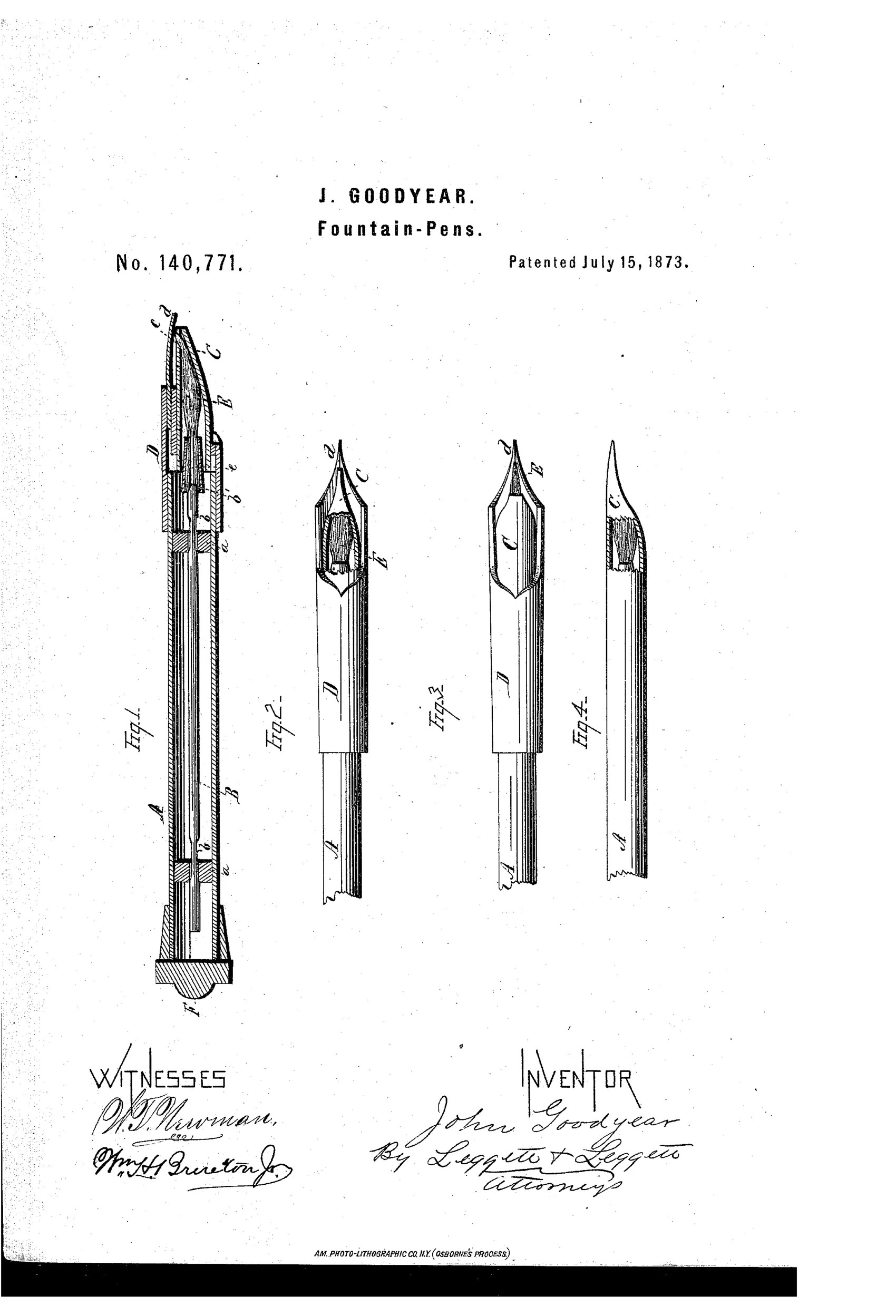
Valve-controlled fountain pen with camel's-hair brush feed
✒ How it works
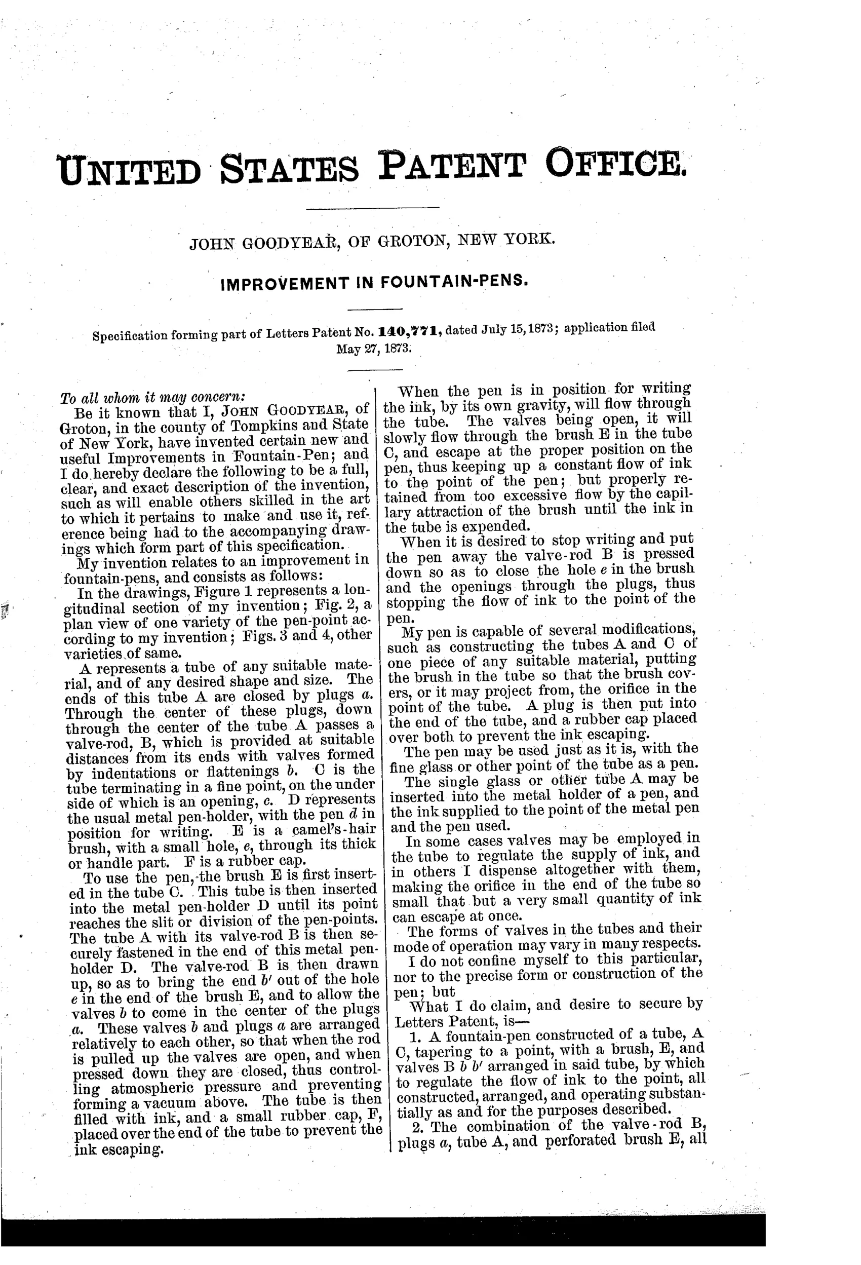
A tube A holds ink and is closed by plugs at each end, with a valve-rod B running through the center that has valves formed by flattenings to control flow. The tube C tapers to a fine point with an opening, and a camel's-hair brush E with a small hole regulates ink flow by capillary attraction into the metal pen-holder D. Pulling up the valve-rod opens the valves to allow ink to flow by gravity through the brush to the pen point; pressing the rod down closes the hole in the brush and stops ink flow. A rubber cap F fits over the end of the tube to prevent ink from escaping when not in use.
✒ What was claimed
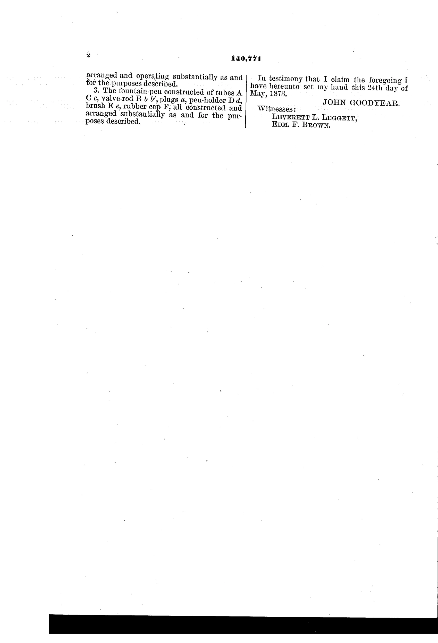
“A fountain-pen constructed of a tube, A C, tapering to a point, with a brush, E, and valves B b b' arranged in said tube, by which to regulate the flow of ink to the point, all constructed, arranged, and operating substantially as and for the purposes described.”
In plain English: The pen consists of a tapered tube fitted with a brush and valves that control the flow of ink to the writing point.
✒ In the inventor’s words
“The pen may be used just as it is, with the fine glass or other point of the tube as a pen.”— John Goodyear, from the specification
Paper patent — likely never produced
No maker, marking, or surviving example of a brush-fed valve pen like this is documented, and the fussy hand-valve design makes commercial production unlikely — a marked specimen would overturn this.
✒ Commentary
This is the pre-Waterman era in miniature: the inventor knows the problem is regulating flow, and he throws two mechanisms at it at once. A valve-rod runs the length of the barrel — pull it up and flattened sections on the rod open passages so ink flows by gravity; press it down and it plugs the outlet. Then, downstream of the valve, a tuft of camel's hair sits in the tapered tip to meter the ink by capillary attraction. Goodyear has independently arrived at the right physics — capillarity is exactly what a feed needs to exploit — but he's implemented it with a brush, which swells, sheds, clogs, and holds no consistent channel geometry.
The drawing rewards a close look. Figs. 2 through 4 show three different tip varieties, and in each the brush tuft is visible inside the tapered nose, feeding a conventional-looking pen point. Fig. 1 shows the whole assembly: valve rod down the bore, plugs at both ends, rubber cap over the tip for transport. The specification even allows using the bare tapered tube — 'the fine glass or other point of the tube as a pen' — a stylographic idea a few years before Cross and MacKinnon made it a category.
As writing hardware it would be temperamental: gravity feed gated by a hand-operated rod means the user, not the pen, decides when ink comes. That's the tell of the doomed generation. Waterman's insight was making the exchange of air and ink automatic; Goodyear still needs a valve and a thumb.
Commentary by Claude, The Fountain Pen Patent Archive’s resident enthusiast