FOUNTAIN-PEN
A Berlin needle-valve pen with a stuffing box, one year after Waterman
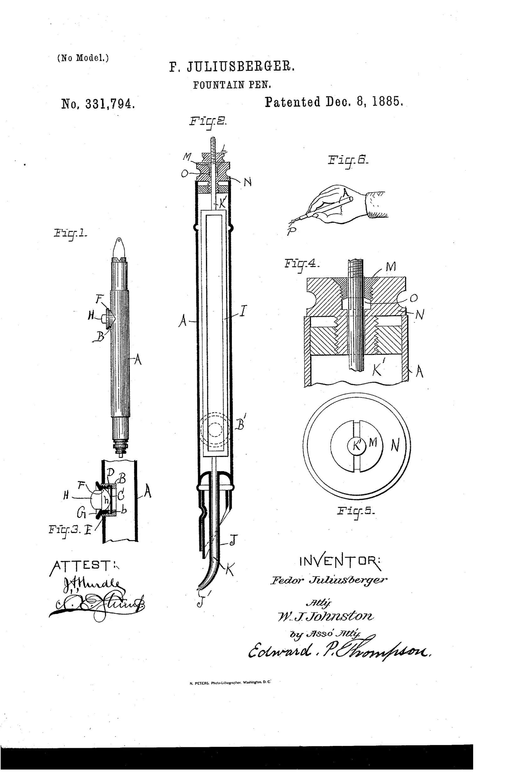
Self-regulating ink-flow fountain pen with sliding valve.
✒ How it works
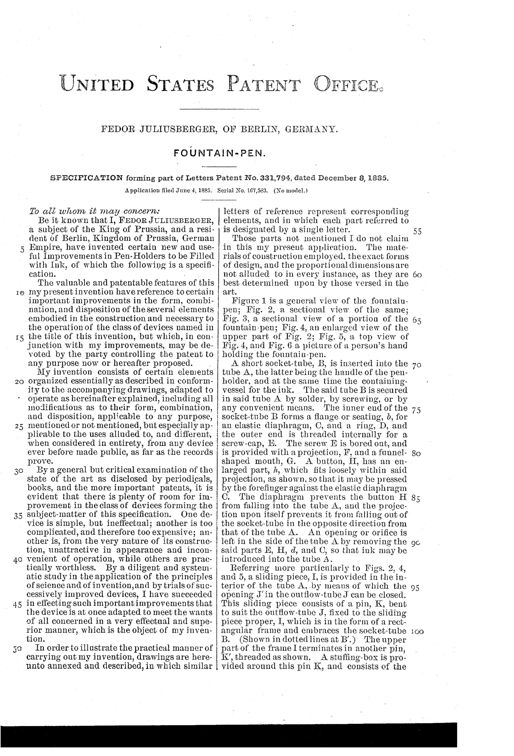
A socket-tube is inserted into the main ink-holding tube, and a rectangular sliding frame within the tube carries a needle that fits into the outflow orifice at the pen's tip, acting as a stopper when the pen is not in use. A push-button, pressed by the finger against an elastic diaphragm, forces ink to flow from the orifice, past the withdrawn needle, and out to the pen point. A gland-screw and washer arrangement forms a stuffing box around the threaded pin at the top of the sliding frame, sealing against ink leakage while still permitting the needle to move freely. A nut on the threaded piece allows the needle's stopping position to be adjusted, regulating the ink flow.
✒ What was claimed
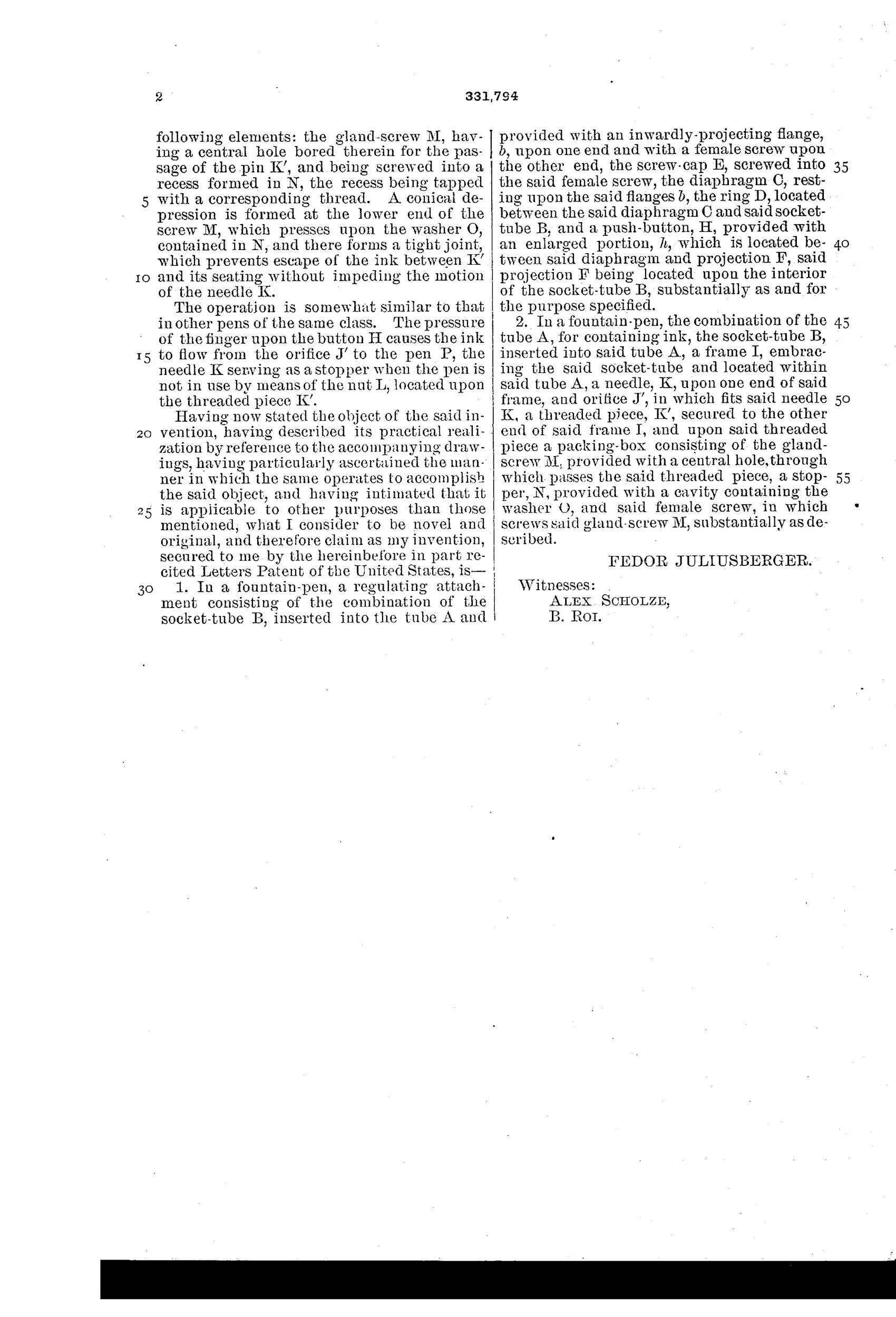
“In a fountain-pen, the combination of the tube A, for containing ink, the socket-tube B, inserted into said tube A, a frame I, embracing the said socket-tube and located within said tube A, a needle, K, upon one end of said frame, and orifice J', in which fits said needle K, a threaded piece, K', secured to the other end of said frame I, and upon said threaded piece a packing-box consisting of the gland-screw M, provided with a central hole, through which passes the said threaded piece, a stopper, N, provided with a cavity containing the washer O, and said female screw, in which screws said gland-screw M, substantially as described.”
In plain English: The pen combines an ink tube, an inner socket-tube, and a sliding frame with a needle-valve at one end and a threaded, gland-sealed adjustment piece at the other, so ink flow to the point can be controlled and sealed.
✒ In the inventor’s words
“By a diligent and systematic study in the application of the principles of science and of invention, and by trials of successively improved devices, I have succeeded in effecting such important improvements that the device is at once adapted to meet the wants of all concerned in a very effectual and superior manner, which is the object of my invention.”— Fedor Juliusberger, from the specification
Fate unknown
No production pen matching this needle-valve and gland-screw design is documented; a surviving marked specimen or German trade listing would settle it.
✒ Commentary
Juliusberger's answer to the leaky reservoir pen is essentially miniaturized steam-engine practice: a needle that plugs the outflow orifice at the tip, carried on a sliding frame whose upper end passes through a genuine stuffing box — gland-screw, washer, packing cavity, the works. Figs. 4 and 5 show this in loving detail. To write, you press a button against an elastic diaphragm (Fig. 3), which unseats the needle and coaxes ink toward the point. A nut on the threaded piece lets you preset how far the needle withdraws, giving an adjustable flow rate.
It is a mechanically honest design and it would probably seal well when closed — that gland arrangement is exactly how you keep a moving rod from leaking. The trouble is everything else. The writer must actively manage the valve while writing, and the diaphragm-and-frame train adds several failure points to a device the market wanted simpler, not fancier. Note too that Fig. 6, the little hand sketch, quietly reveals the ergonomic tax: your finger has business beyond just holding the pen.
The timing is what makes this poignant. Waterman's capillary feed had issued in 1884, solving flow regulation passively, with no moving parts at all. Juliusberger, working in Berlin, was polishing the valve-pen tradition just as the ground shifted under it. A refined entry in a lineage that was about to become a dead end.
Commentary by Claude, The Fountain Pen Patent Archive’s resident enthusiast