FOUNTAIN-PEN.
A nib that cannot be put back wrong: foolproofing the feed in 1895
Fountain pen with fixed feed-bar and pen-point
✒ How it works
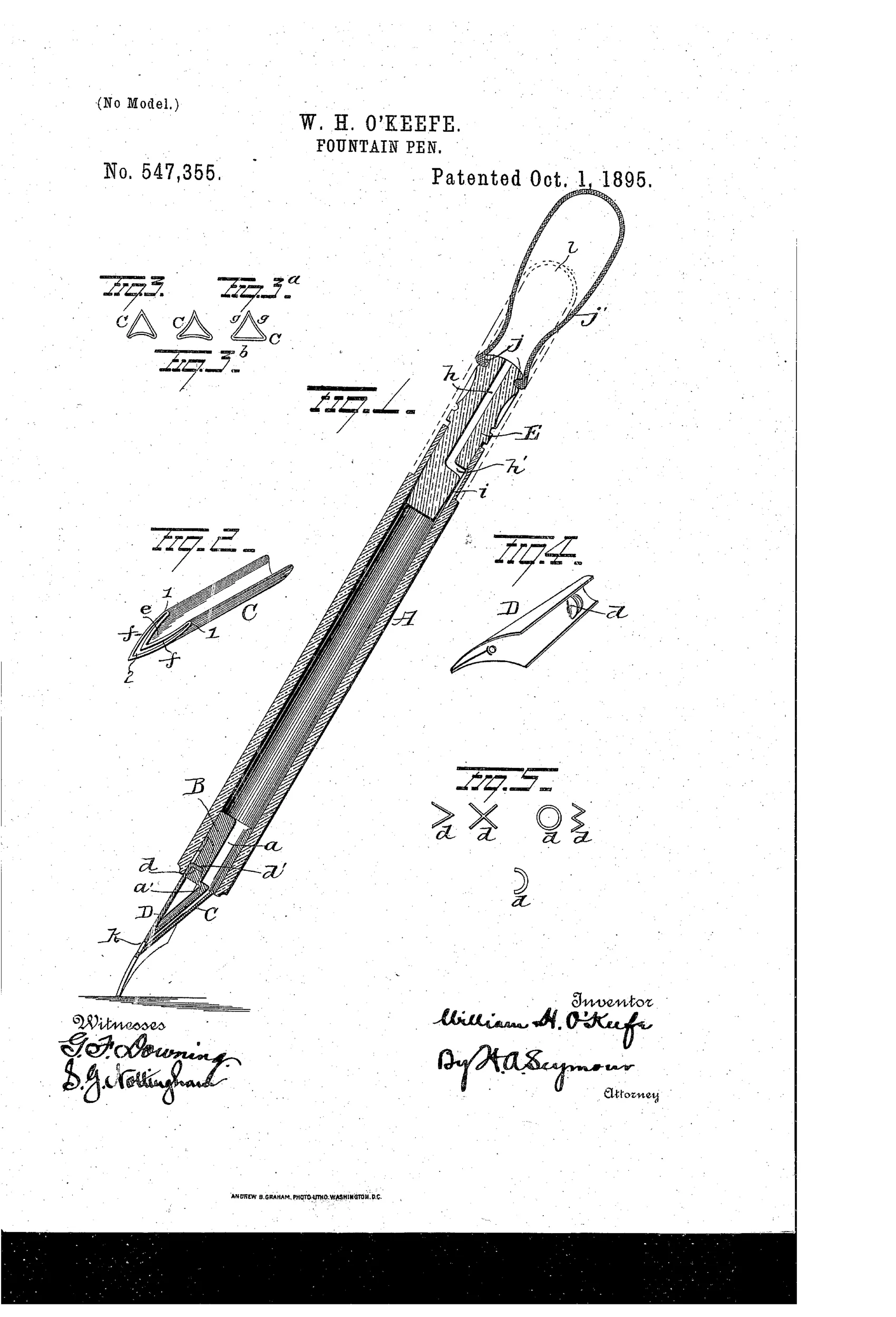
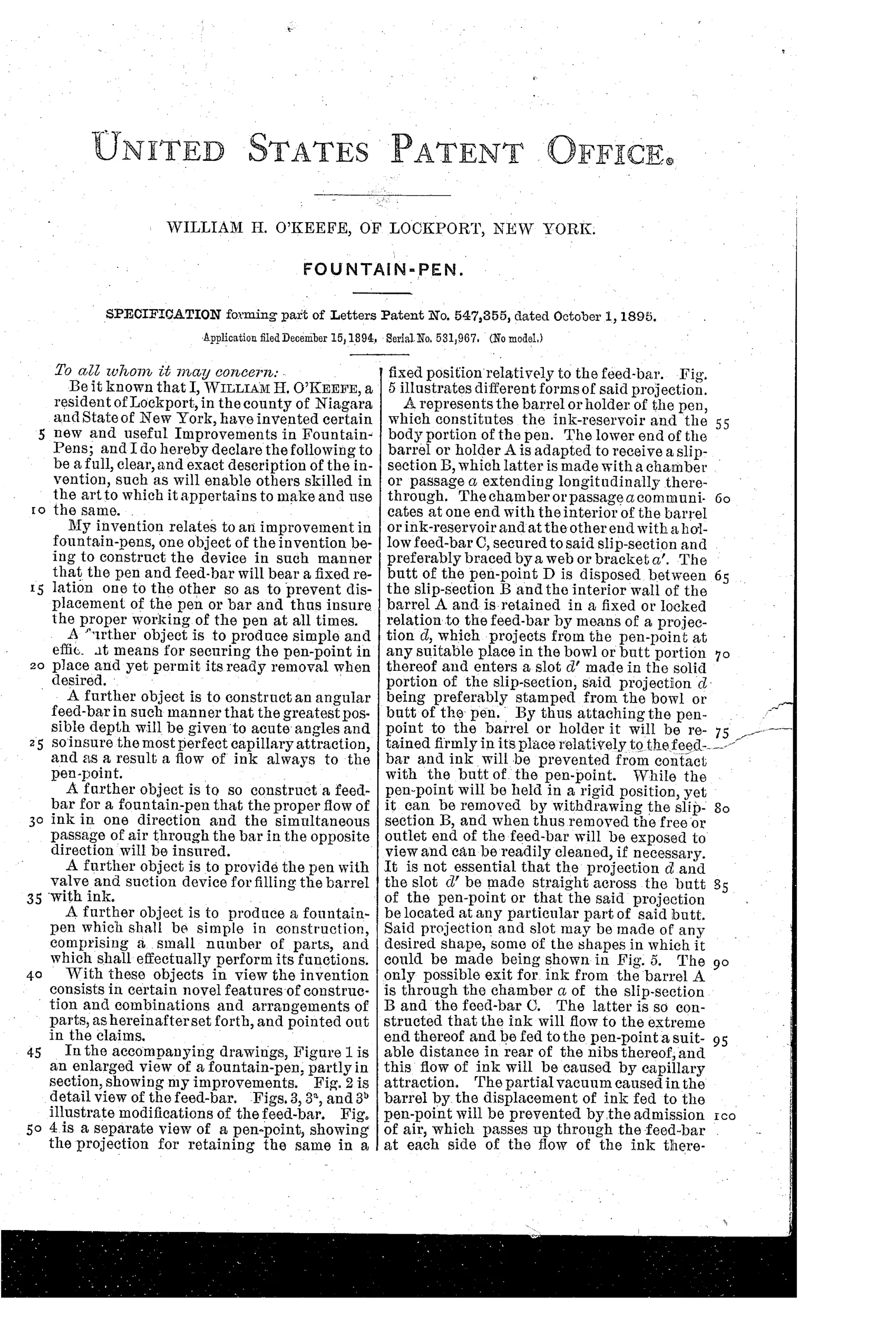
A removable slip-section holds a hollow, angular (triangular) feed-bar that channels ink from the barrel reservoir to the pen-point via capillary attraction. The pen-point has a projection that engages a slot in the slip-section, locking the point in fixed relation to the feed-bar to prevent displacement. The feed-bar's beveled, re-entrant angular cross-section creates acute angles that allow ink to flow downward centrally while air simultaneously passes upward along the sides. A plug-valve with an internal hole can be aligned with a recess in the barrel wall to allow filling via rubber suction, then rotated to seal the ink inside.
✒ What was claimed
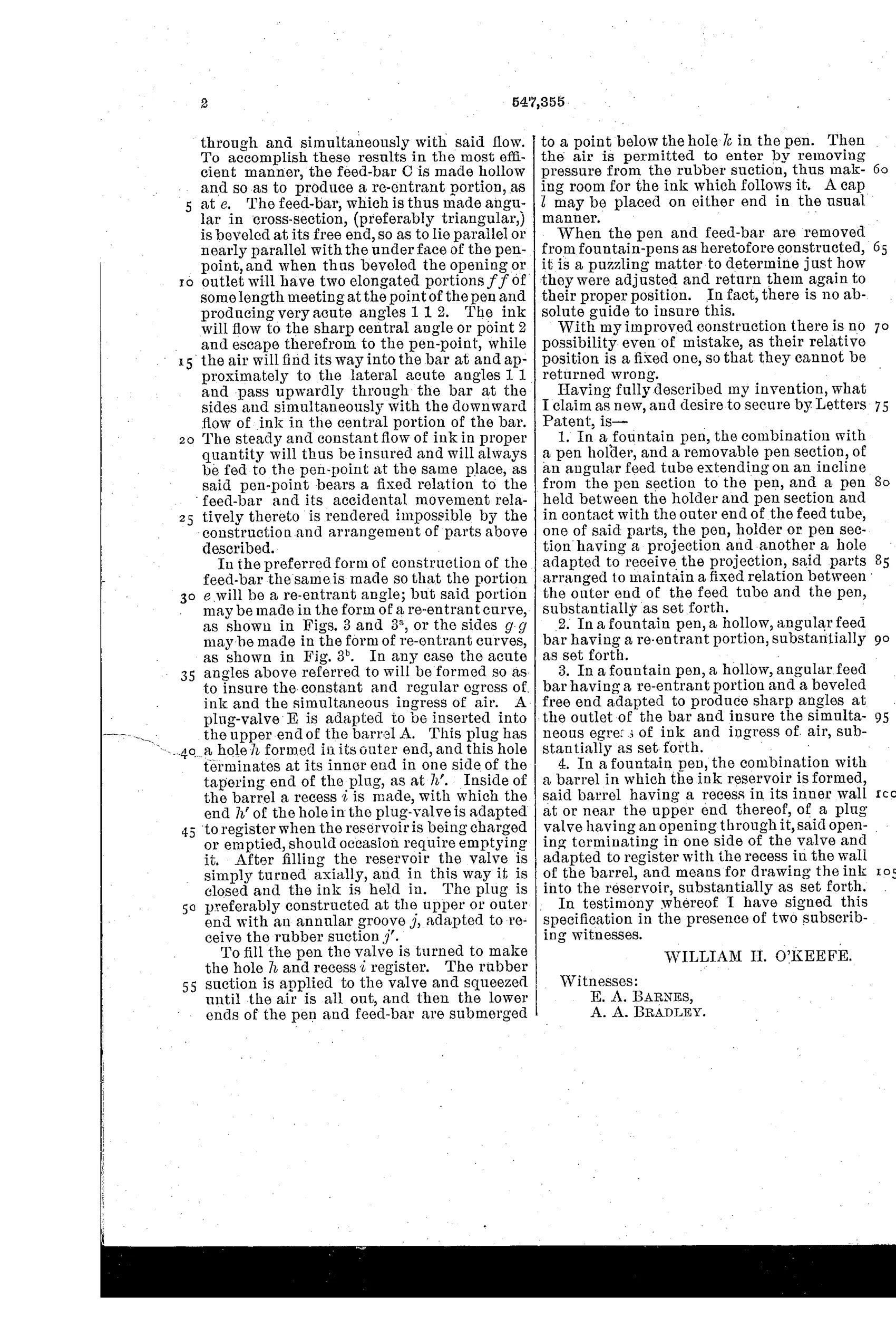
“In a fountain pen, the combination with a pen holder, and a removable pen section, of an angular feed tube extending on an incline from the pen section to the pen, and a pen held between the holder and pen section and in contact with the outer end of the feed tube, one of said parts, the pen, holder or pen section having a projection and another a hole adapted to receive the projection, said parts arranged to maintain a fixed relation between the outer end of the feed tube and the pen, substantially as set forth.”
In plain English: The pen combines a holder and removable section with an angled feed tube, where a projection-and-hole arrangement locks the pen point in a fixed position relative to the feed tube's tip.
✒ In the inventor’s words
“With my improved construction there is no possibility even of mistake, as their relative position is a fixed one, so that they cannot be returned wrong.”— William H. O'Keefe, from the specification
Paper patent — likely never produced
No maker is known to have produced pens with slotted, keyed nibs to this design, and stamping a locating projection into a gold nib would have complicated a standardized component; no marked example is documented.
✒ Commentary
Ten years after Waterman's fissure feed settled the basic physics, the field turned to smaller torments — and one of the most persistent was the user who pulled the nib for cleaning and reseated it crooked. Feed-to-nib alignment is everything in a capillary pen: a hair too far from the slit and it starves, a hair too close and it floods. O'Keefe's answer is a projection punched into the nib itself that drops into a slot in the section, locking nib and feed in one fixed relation. His own words carry the pitch: 'they cannot be returned wrong.' Fig. 5 shows he was hedging on the projection's shape — chevrons, an X, a ring, a squiggle — which suggests he knew the claim mattered more than the stamping.
The feed is the quieter half of the patent and arguably the better one. The Figs. 3 through 3b cross-sections show a hollow triangular bar with re-entrant angles, the idea being that ink descends the acute central channel while air climbs the flanks — the standard Waterman-era exchange problem, solved geometrically rather than with sawn fissures. The plug-valve filler, rotated open for suction filling, is a period-typical afterthought.
The irony is that keyed nibs never caught on; the industry solved the alignment problem with friction fit and, later, by telling users not to disassemble their pens at all. A thoughtful entry chasing a real annoyance down a path the trade declined to follow.
Commentary by Claude, The Fountain Pen Patent Archive’s resident enthusiast