IMPROVEMENT IN FOUNTAIN-PENS
A string-wick feed and leather-lined reservoir, twenty-three years before Waterman
Early self-filling ink fountain pen
✒ How it works
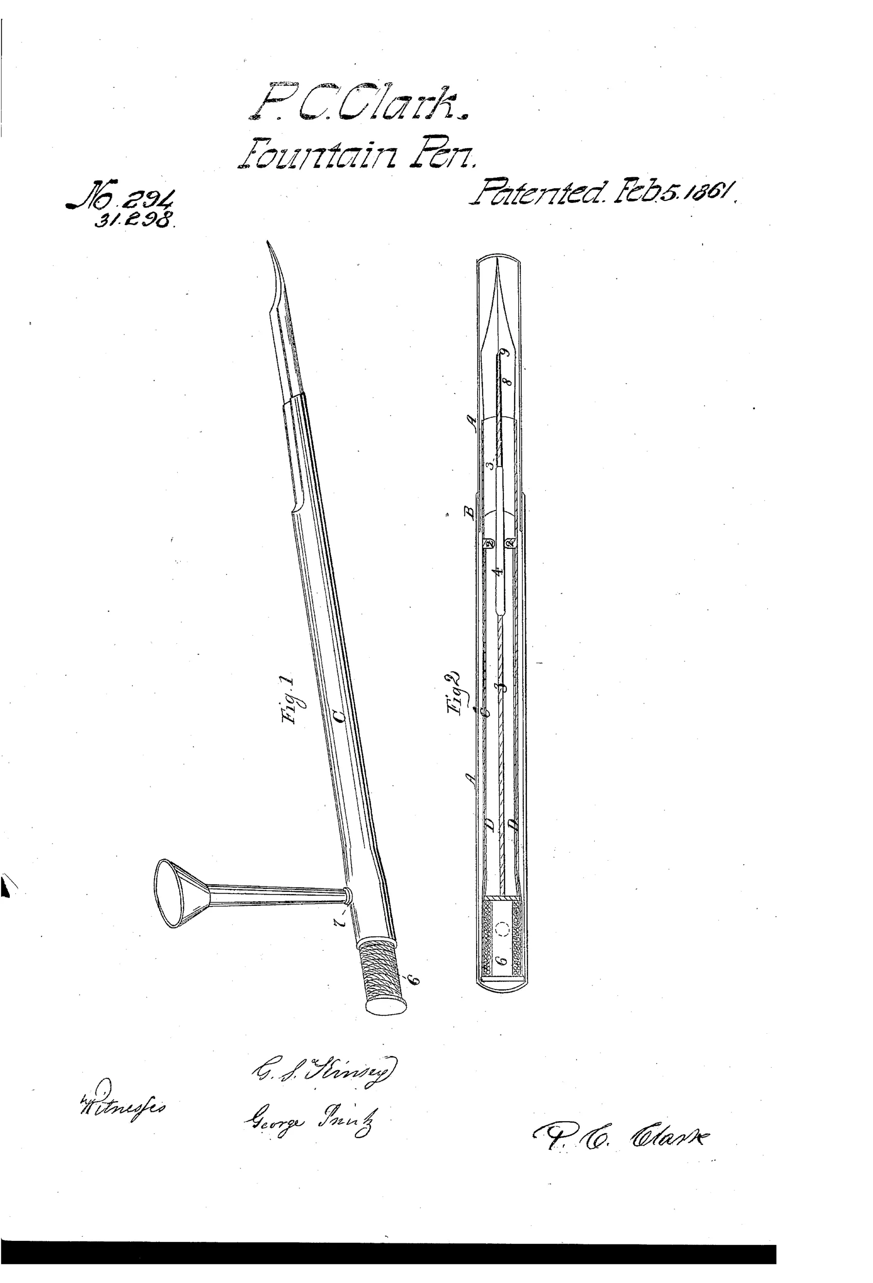
The pen holder contains an internal ink fountain lined with morocco leather to protect the metal from corrosion. A conducting-rod fitted with a flexible flannel valve and a threaded string runs through the holder to the pen point, regulating ink flow by capillary action along the thread. A skeleton piston-head packed with cotton twine slides within the case to admit air and let ink descend by gravity. To refill, the piston is drawn past a filling-tube so a funnel can introduce ink while air escapes, then the piston reseals the fountain.
✒ What was claimed
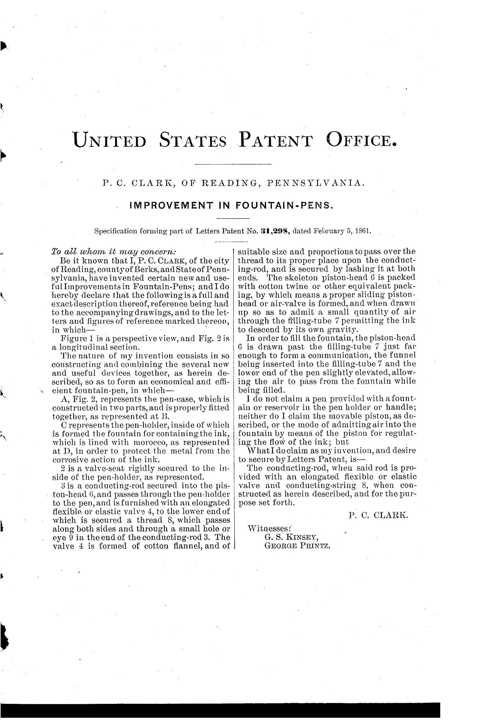
“The conducting-rod, when said rod is provided with an elongated flexible or elastic valve and conducting-string 8, when constructed as herein described, and for the purpose set forth.”
In plain English: The claimed invention is the ink-conducting rod fitted with a flexible valve and a wicking string that draws ink down to the nib by capillary action.
✒ In the inventor’s words
“The skeleton piston-head 6 is packed with cotton twine or other equivalent packing, by which means a proper sliding piston-head or air-valve is formed, and when drawn up so as to admit a small quantity of air through the filling-tube 7 permitting the ink to descend by its own gravity.”— P. C. Clark, from the specification
Paper patent — likely never produced
No surviving example or maker is documented, and the leather-lined metal fountain with a separate filling funnel is the kind of construction that rarely got past the model stage; a marked specimen would overturn this.
✒ Commentary
This is the pre-Waterman stratum in its purest form: an 1861 inventor who understood the problem — ink won't flow steadily unless air can get in — and reached for the materials of his day to solve it. Clark's answer to feed regulation is a conducting-rod wrapped with a thread, so ink creeps down to the nib by capillary action along the string. That's genuinely the right physical insight; it's the same capillarity Waterman would later harness with cut channels in hard rubber. Clark just did it with twine.
The section in Fig. 2 rewards a slow look. There's a flexible flannel valve on the rod, a skeleton piston-head packed with cotton twine acting as a sliding air valve, and a filling-tube arrangement: draw the piston past the port, pour ink through the funnel shown dangling in Fig. 1, and reseal. That's a self-contained filling system in 1861, when most reservoir pens were charged with a dropper and a prayer.
The morocco leather lining of the fountain — to keep corrosive iron-gall ink off the metal — tells you why these pens were doomed. The era lacked hard rubber barrel construction, so inventors armored metal with organic materials that ink would eventually rot. A fascinating, characteristic dead end: right physics, wrong materials, and a filling ritual involving a loose funnel that no pocket would forgive.
Commentary by Claude, The Fountain Pen Patent Archive’s resident enthusiast