FOUNTAIN-PEN
Three separate ink paths and a short bore, nine years into the feed wars
Improved leak-resistant fountain pen ink feed
✒ How it works
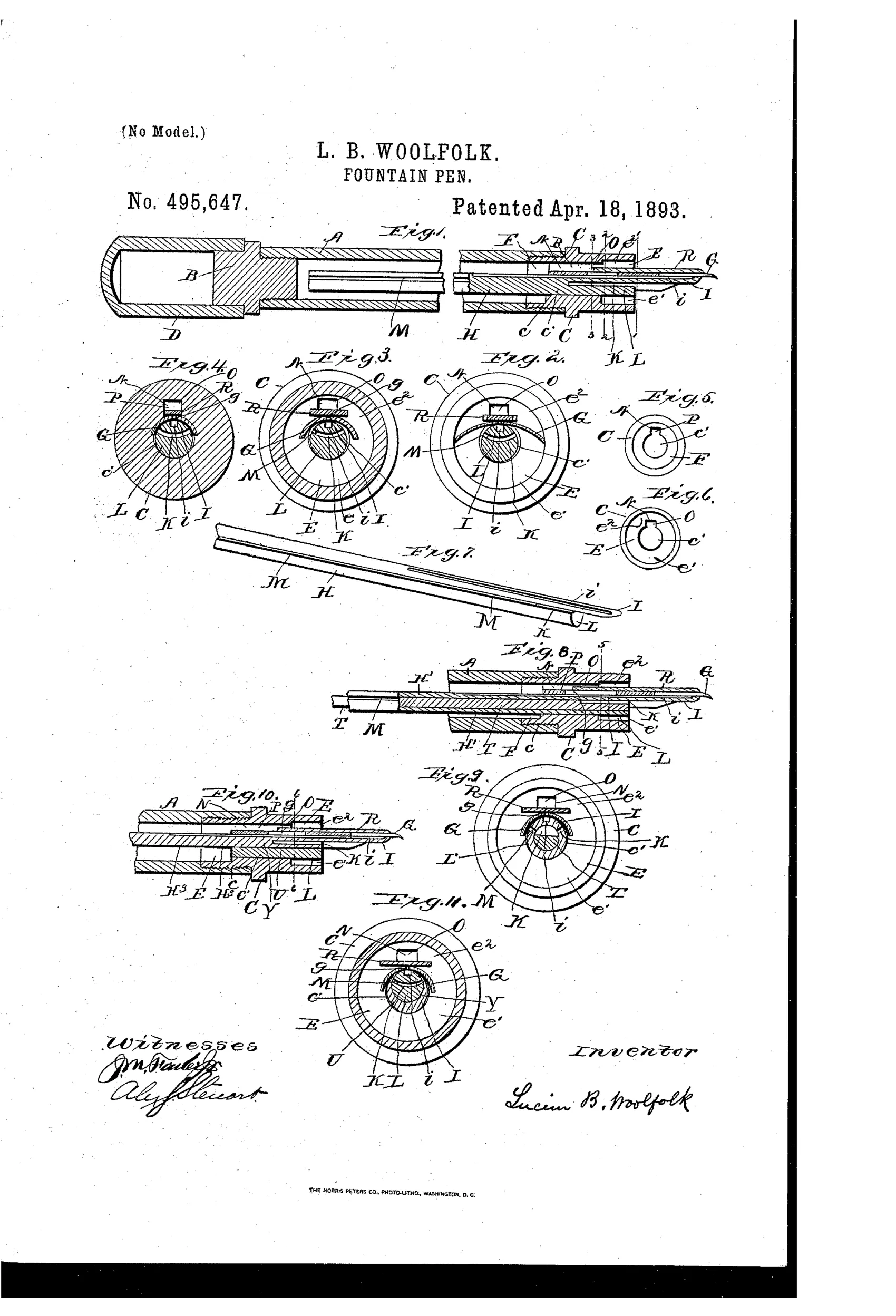
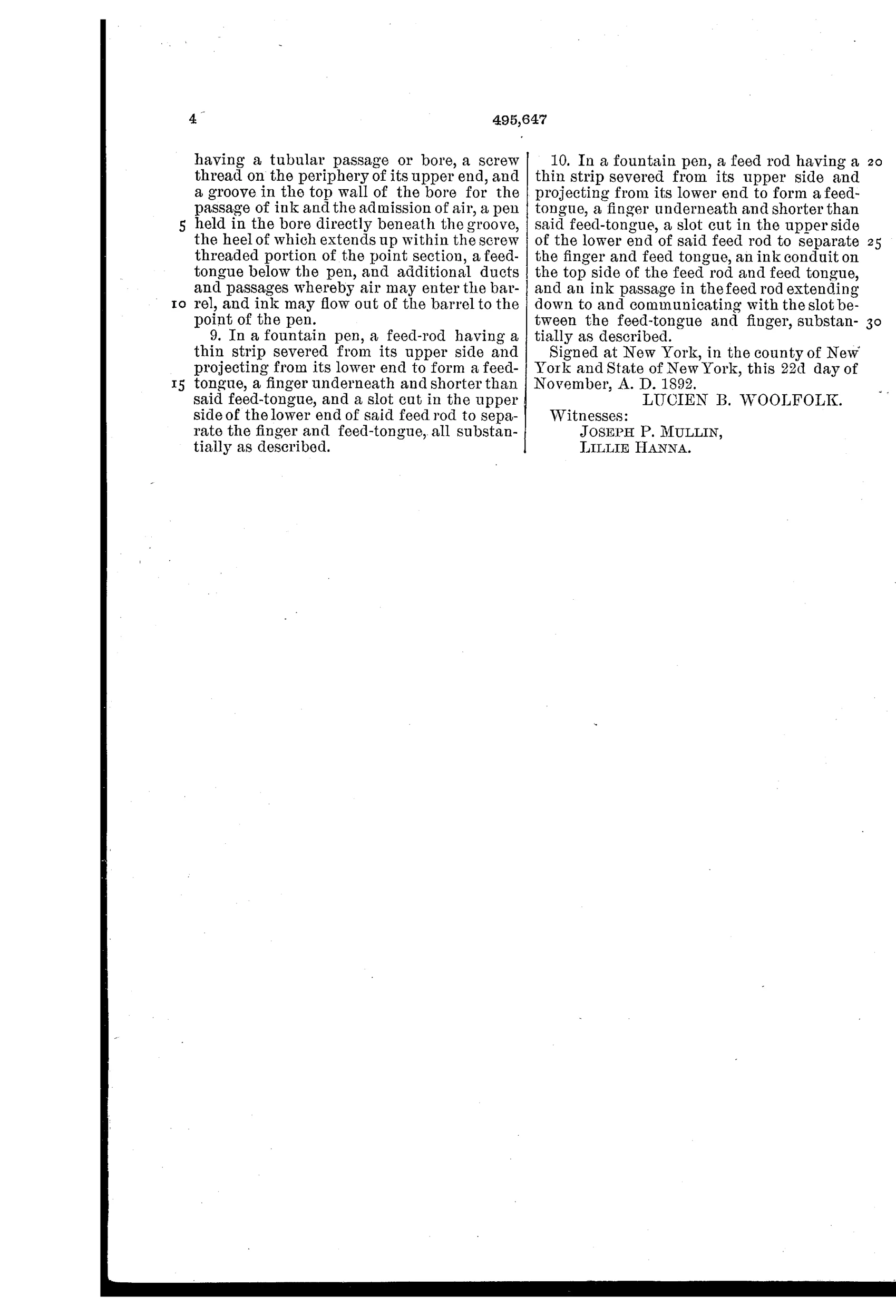
The barrel is closed at its upper end by a plug and joined to a short tubular point section whose bore is only long enough to hold the pen. A solid feed rod fits in the bore below the pen, having an integral thin feed-tongue on top separated by a slot from a larger finger beneath, with grooves forming ink conduits and an ink passage. A groove cut in the upper wall of the bore forms an ink way and air inlet, with an ink conveyer strip held in the groove behind the pen to gather overflow ink and prevent skipping. Ink flows to the point through three separate paths (through the feed-tongue conduit, through the separating slot, and through the ink way and ink aperture in the pen), while air enters through an antechamber and air inlet, keeping the ink and air flows from interfering with each other.
✒ What was claimed
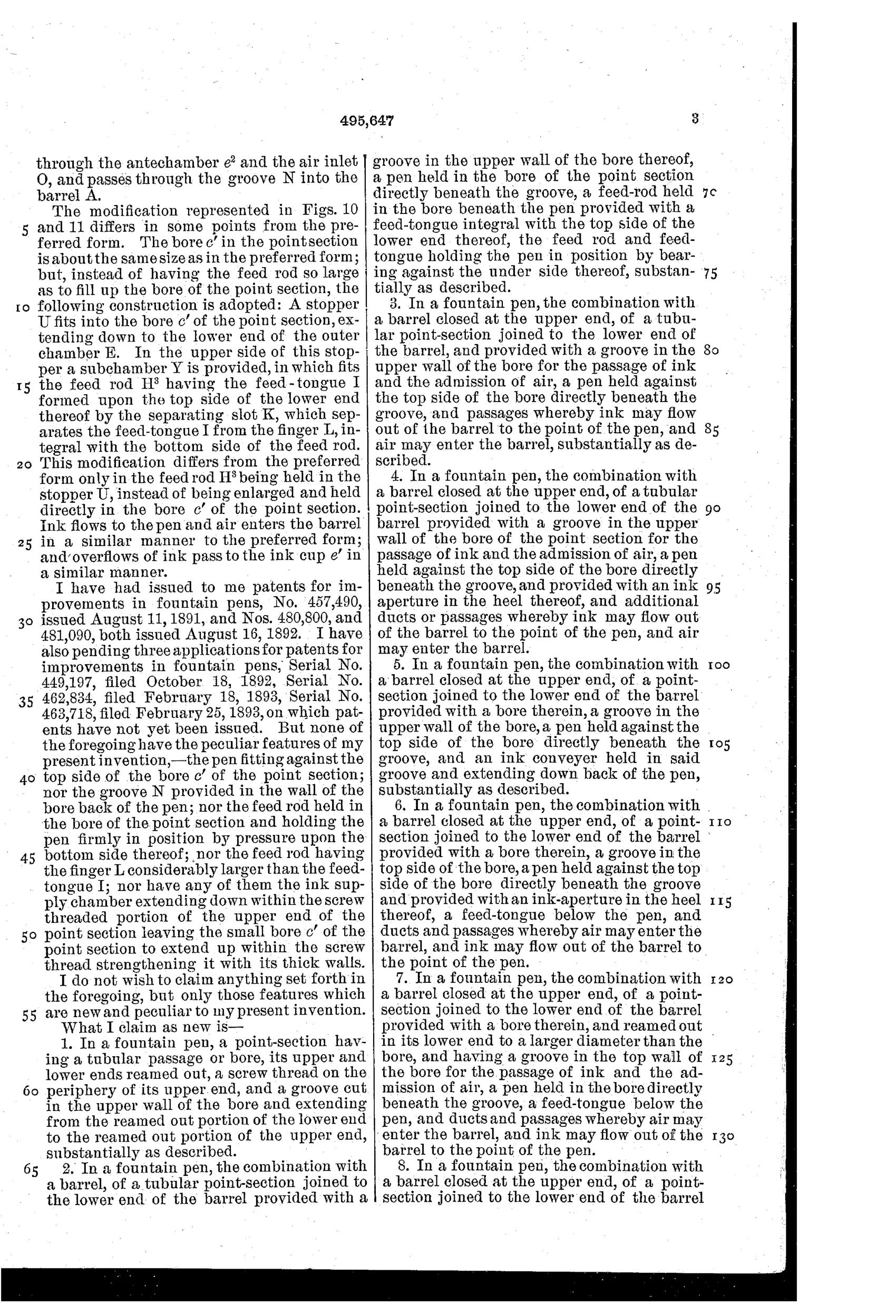
“In a fountain pen, the combination with a barrel closed at the upper end, of a tubular point-section joined to the lower end of the barrel, and provided with a groove in the upper wall of the bore for the passage of ink and the admission of air, a pen held against the top side of the bore directly beneath the groove, and passages whereby ink may flow out of the barrel to the point of the pen, and air may enter the barrel, substantially as described.”
In plain English: The pen combines a closed barrel, a short point-section with a bore having a top groove for ink and air, a pen held against the top of the bore beneath that groove, and passages letting ink flow out to the point while air enters the barrel.
✒ In the inventor’s words
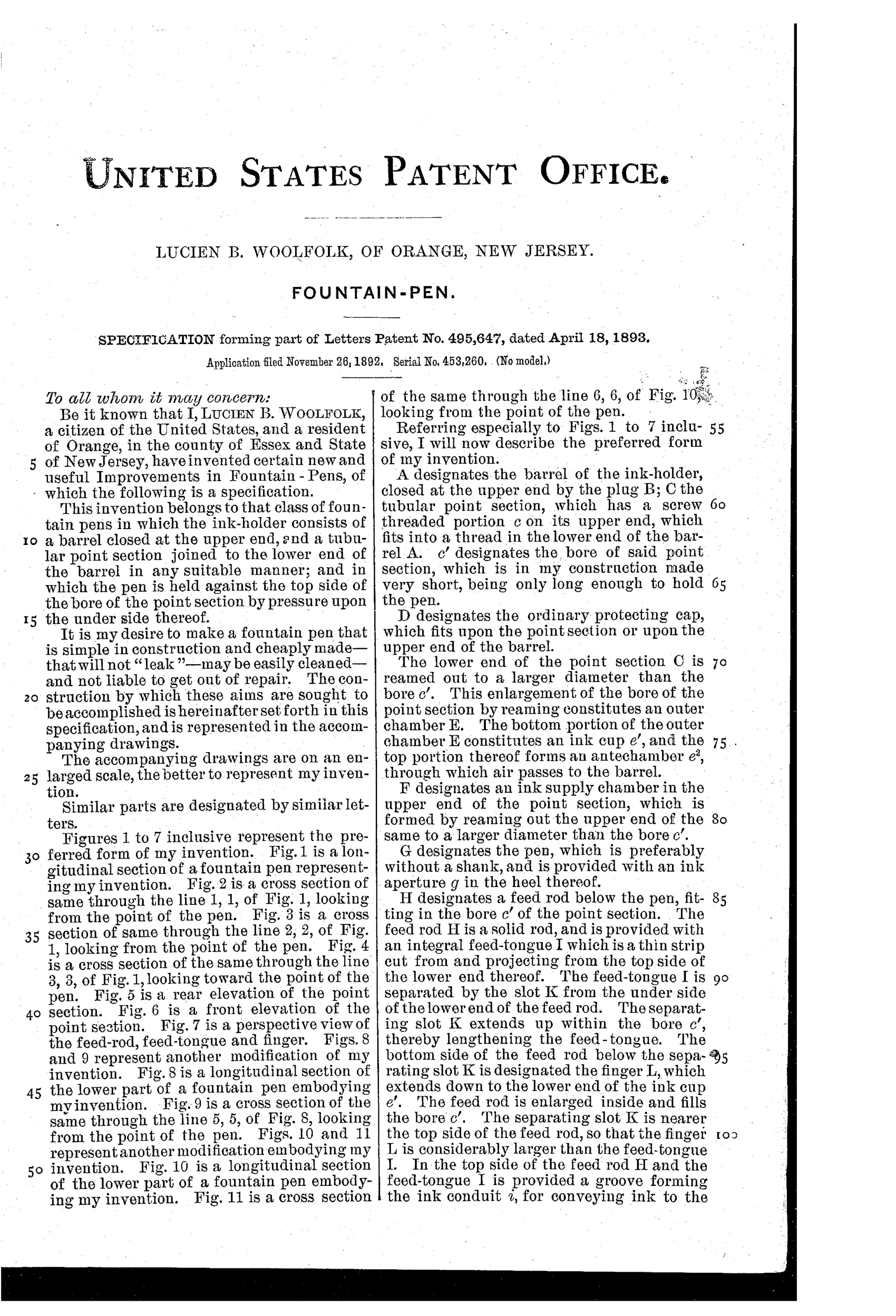
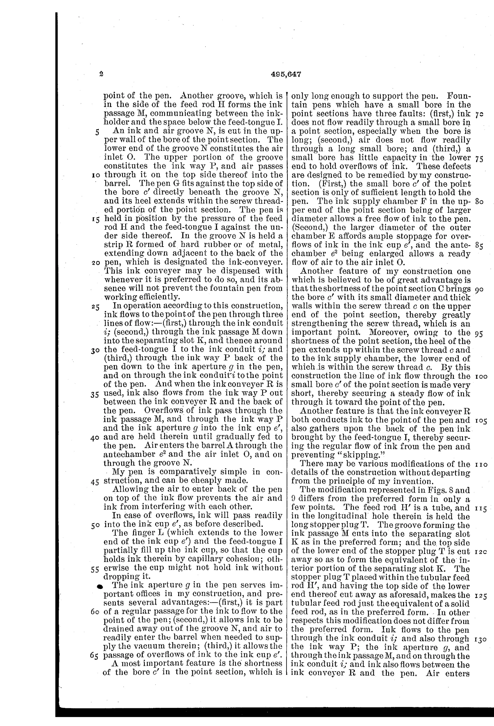
“Fountain pens which have a small bore in the point sections have three faults: (first,) ink does not flow readily through a small bore in a point section, especially when the bore is long; (second,) air does not flow readily through a long small bore; and (third,) a small bore has little capacity in the lower end to hold overflows of ink.”— Lucien B. Woolfolk, from the specification
Fate unknown
No Woolfolk-marked pen or licensee is documented to my knowledge; a surviving example with this feed rod would settle it.
✒ Commentary
Woolfolk starts from a diagnosis rather than a gadget, and his opening complaint is worth reading: long, narrow bores in the point section choke both ink and air, and leave nowhere for overflow to pool. His fix is to shorten the bore to just what's needed to grip the nib, then multiply the plumbing — ink can reach the point through a conduit in the feed-tongue, through the slot between tongue and finger, and through a groove cut in the top of the bore that doubles as the air inlet. An 'ink conveyer' strip tucked behind the pen catches surplus before it can blob onto the paper.
The redundancy is the interesting part. Waterman's 1884 insight was that one well-made capillary channel, exchanging air for ink, was enough. Woolfolk hedges instead: if one path stalls, another carries on, and the antechamber tries to keep air and ink traffic from colliding. It's belt-and-suspenders feed design, and Fig. 7's feed rod — a solid rod with an integral thin tongue riding above a heavier finger — is a genuinely tidy piece of hard-rubber work.
The eleven figures, with cross-sections at four stations plus two modified lower parts, show a man iterating seriously. But by 1893 the market was already consolidating around simpler underfeeds, and complexity like this tended to stay on paper. A workmanlike entry in a very crowded decade, distinguished by its honest statement of the problem.
Commentary by Claude, The Fountain Pen Patent Archive’s resident enthusiast