FOUNTAIN-PEN.
A rubber ball dangling on a wire tries to tame the air bubble
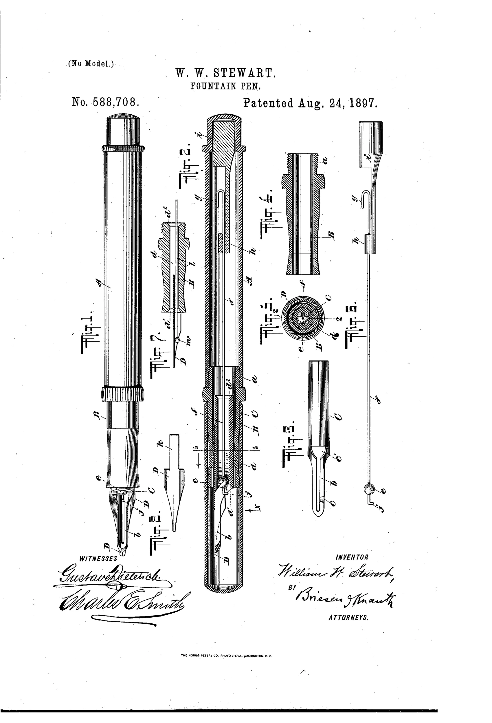
Fountain pen with air-bubble ink-flow regulator
✒ How it works
An angular ink-conduit runs through a feeder-bar and is left with unobstructed openings at its corners even when a ball is inserted. A rubber ball, mounted on a flexible wire that hooks onto a plug at the top of the holder, sits in the bore and is adjustable or fully removable to control ink flow and permit filling. Ink passes along the corners of the bore to a recessed feeder-finger that contacts the pen-nib, while air bubbles pass upward around the ball into the reservoir in a regulated, uniform size. This mechanical obstruction mimics and controls the naturally occurring air bubbles, preventing sweating, bleeding, or uncontrolled ink flow.
✒ What was claimed
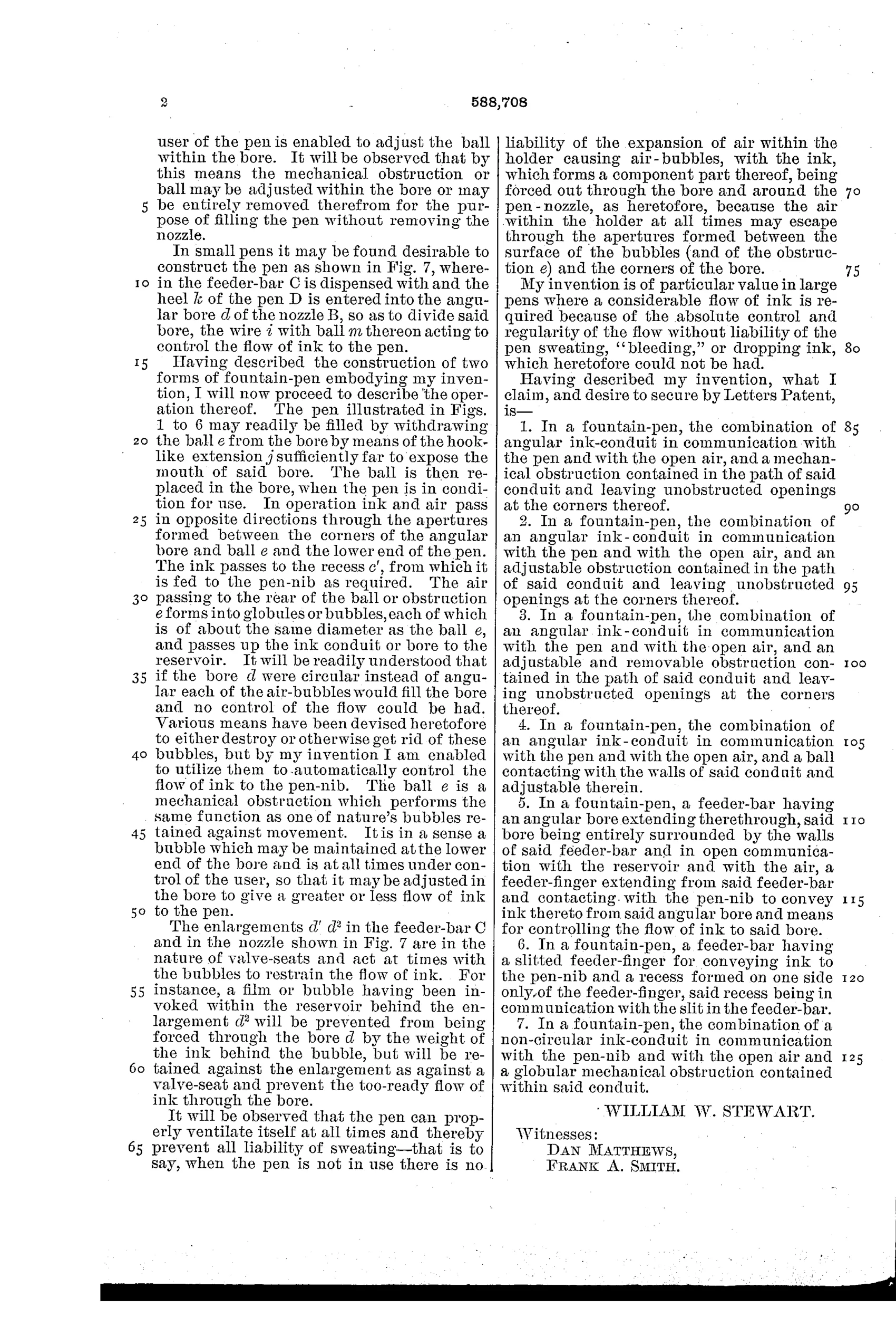
“1. In a fountain-pen, the combination of angular ink-conduit in communication with the pen and with the open air, and a mechanical obstruction contained in the path of said conduit and leaving unobstructed openings at the corners thereof.”
In plain English: The pen uses an angular ink channel with a mechanical obstruction inside it that still leaves gaps at the corners for air and ink to pass.
✒ In the inventor’s words
“My invention is of particular value in large pens where a considerable flow of ink is required because of the absolute control and regularity of the flow without liability of the pen sweating, "bleeding," or dropping ink, which heretofore could not be had.”— William W. Stewart, from the specification
Fate unknown
No pen with this ball-in-bore regulator is documented to a known maker's line; a marked specimen or trade advertisement would settle it.
✒ Patented the same day
- FOUNTAIN-PEN. — William W. Stewart
✒ More by William W. Stewart
- FOUNTAIN STYLUS-PEN. (1884)
- FOUNTAIN PEN-HOLDER. (1886)
- FOUNTAIN-PEN. (1897)
- FOUNTAIN-PEN (1899)
✒ Commentary
By 1897 everyone in the trade knew that Waterman's insight — ink out, air in, through the same capillary channels — was the key to a pen that didn't drool. Stewart's patent takes that insight literally and builds a machine around the bubble itself. His angular bore holds a small rubber ball on a flexible wire, hooked to a plug at the top of the barrel. The ball nearly fills the round part of the passage, but the corners of the angular bore stay open: ink slips down the corners while air bubbles squeeze up past the ball in what he claims is a regulated, uniform size. It is bubble metering by mechanical throttle.
Look at Fig. 5, the cross-section, to see the trick clearly — a round ball in a polygonal hole, with the corner gaps doing the work. Fig. 6 shows the ball-and-wire assembly, which is also removable for filling and adjustable for flow, a genuinely thoughtful touch for the eyedropper era.
The worry is the ball itself. Soft rubber sitting permanently in iron-gall ink is not a long-term proposition, and a valve that swells or hardens becomes a plug. Stewart's stated aim — big pens with heavy flow that don't sweat or bleed — was a real problem, but the industry's answer turned out to be smarter passive feeds, not moving parts in the ink channel. A clever dead end, and an honest one.
Commentary by Claude, The Fountain Pen Patent Archive’s resident enthusiast