FOUNTAIN-PEN
A perforated tube coiled into a cone, promising a dip pen's independence from the inkwell
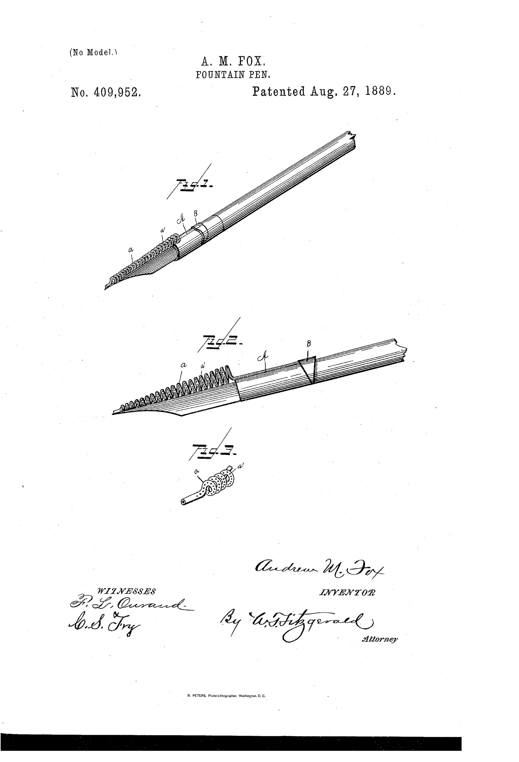
Spiral-tube ink reservoir attachment for pens
✒ How it works
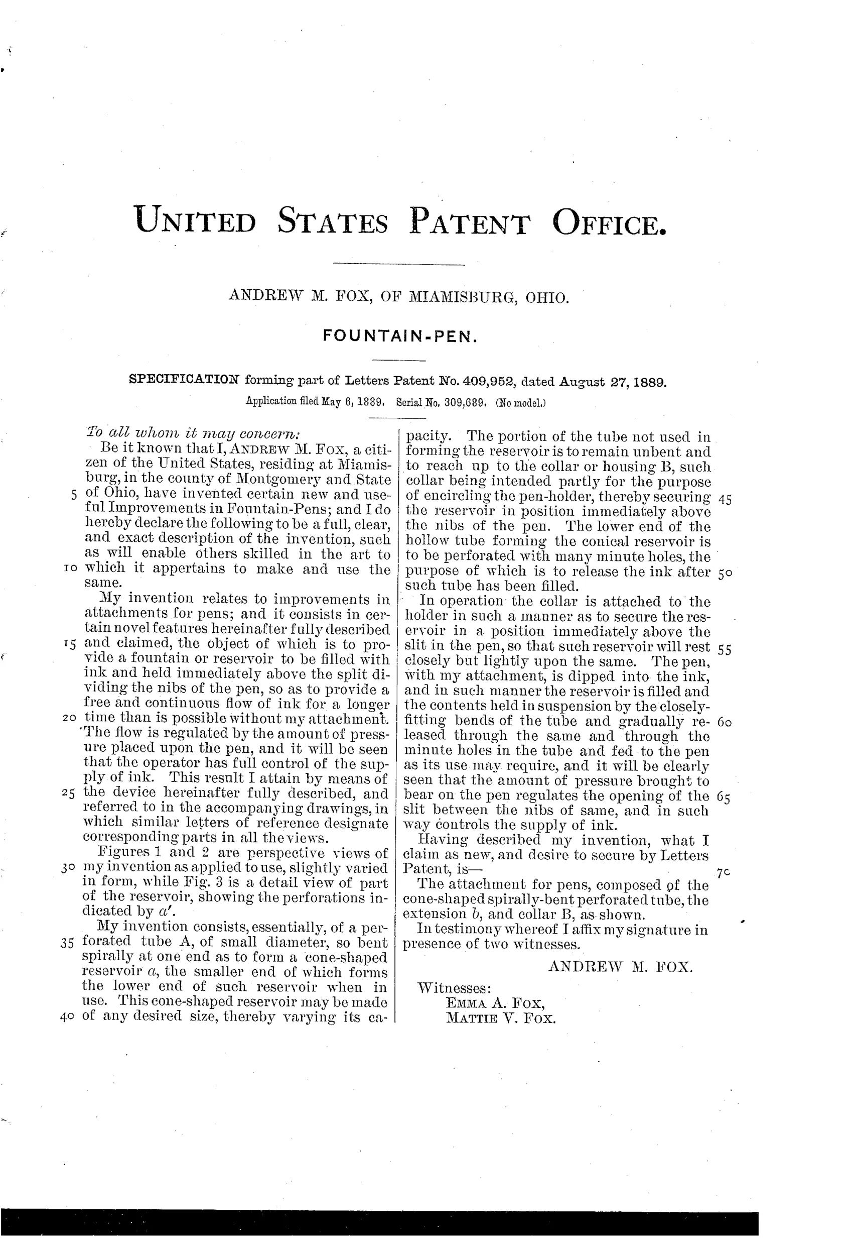
The device consists of a small-diameter perforated tube bent spirally at one end to form a cone-shaped ink reservoir. The lower end of the cone forms the tip that sits above the split in the pen's nibs, while the unbent portion of the tube extends up to a collar that secures it to the pen holder. The lower end of the reservoir tube is perforated with many minute holes so that ink is gradually released and fed to the pen. Pressure on the pen controls the opening of the slit between the nibs, thereby regulating the supply of ink from the reservoir.
✒ What was claimed
“The attachment for pens, composed of the cone-shaped spirally-bent perforated tube, the extension b, and collar B, as shown.”
In plain English: The invention is a pen attachment made of a cone-shaped, spirally bent, perforated tube with an extension and a collar, as illustrated.
✒ In the inventor’s words
“The flow is regulated by the amount of pressure placed upon the pen, and it will be seen that the operator has full control of the supply of ink.”— Andrew M. Fox, from the specification
Paper patent — likely never produced
Manufacturing a minutely perforated coiled tube as a cheap pen accessory seems implausible, and no marked example or maker association is known to me.
✒ Commentary
Five years after Waterman's feed patent, Andrew Fox of Miamisburg, Ohio is working a different problem entirely. This isn't a fountain pen in the modern sense — it's an attachment for an ordinary steel dip pen: a fine tube pierced with minute holes and wound into a cone-shaped spiral that perches above the nib slit, holding a charge of ink and dribbling it down as you write. Dip once, write longer. It belongs to a whole family of ink-retaining nib attachments that flourished before (and stubbornly alongside) the true fountain pen.
The mechanical idea has a certain elegance. The perforations meter the ink, and Fox claims flow regulation through nib pressure — press harder, the tines spread, the slit widens, more ink comes down. That's real, as far as it goes; it's the same principle every nib exploits. What the drawing quietly reveals is the trouble: Fig. 3 shows the coil sitting fully exposed above the pen, an open reservoir with dozens of tiny holes facing every direction. Nothing but surface tension keeps that ink where it belongs when you set the pen down, shake it, or breathe on it wrong.
By 1889 the capillary feed had already answered the question Fox is asking, and answered it inside a sealed barrel. This is a clever late entry in a race that had ended — workmanlike, sincere, and pointed the wrong way.
Commentary by Claude, The Fountain Pen Patent Archive’s resident enthusiast