STYLOGRAPHIC PEN
A stylographic needle you could tune by hand — spring and pin made one piece
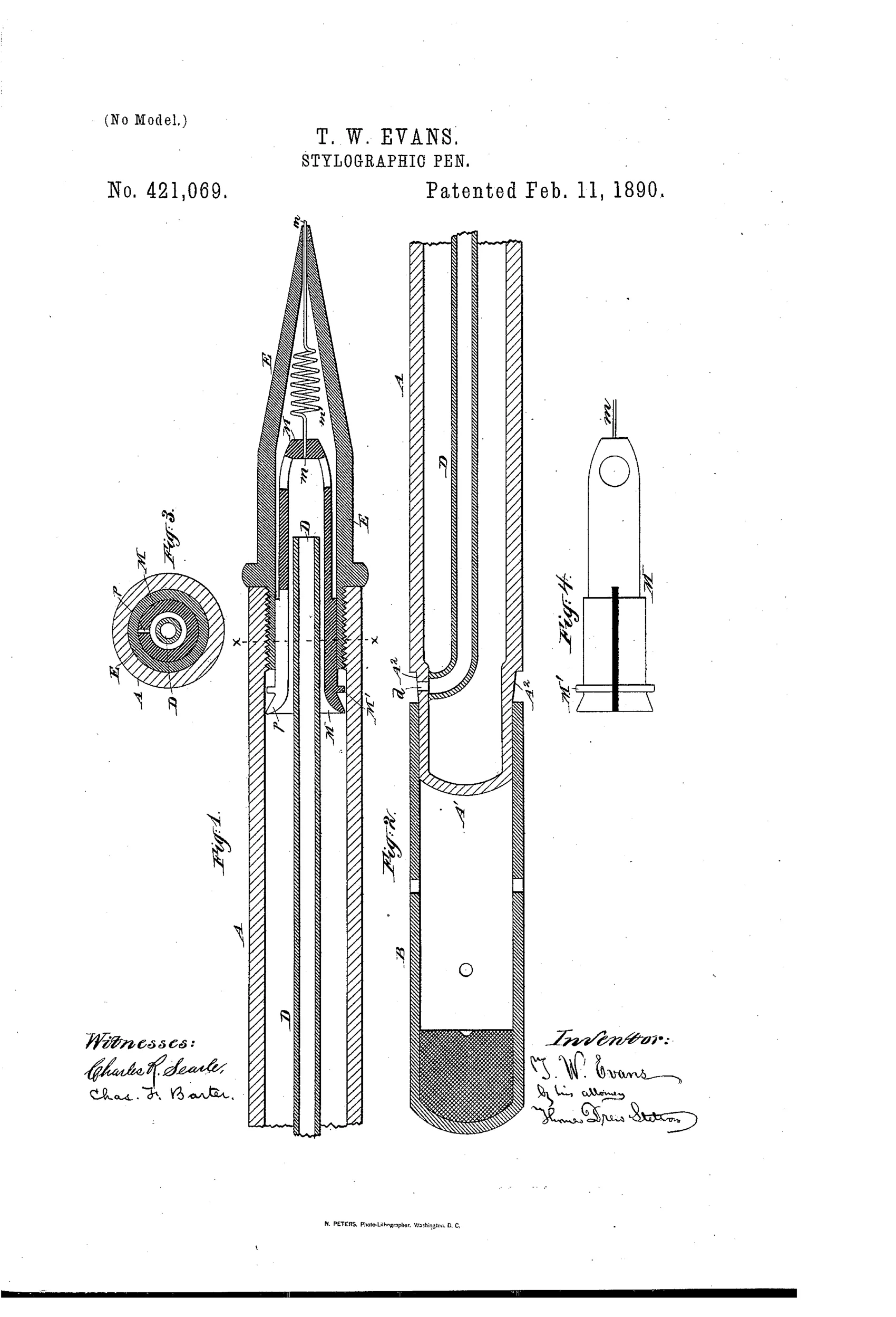
A stylographic (tube-fed) pen with adjustable ink-flow pin
✒ How it works
The pen body A holds a tapered point-piece E through which a small pin m plays in and out to regulate ink flow onto the paper. The pin m is fixed in a hollow carrier M and has an integral coiled spring m' that provides its elastic outward pressure. The carrier M is separate from the internal air-tube D and can be manually drawn out or pushed in to independently adjust how far the pin protrudes, without needing a tool. An orifice d in the tapered upper end lets air enter the air-tube D to replace ink consumed during writing, and a cap B can seal this vent tightly when filling or storing the pen.
✒ What was claimed
“In a stylographic pen, the case A, point-piece E, and air-tube D, combined with the rigid carrier M, separate from the air-tube and adapted to be independently adjusted within the point-piece E, and with the pin m and coil m' integral with said pin, said coil being connected to the rigid adjustable carrier M, substantially as described.”
In plain English: The pen combines a case, point-piece, and air-tube with a separate rigid carrier that can be independently adjusted to move a pin (with its integral coil spring) in and out of the point-piece to control ink flow.
✒ In the inventor’s words
“The elastic action of the point is more lively and mobile than in ordinary pens, because of the small inertia and friction involved in the motion as it yields to the inequalities of pressure in the act of writing.”— Thomas W. Evans, from the specification
Fate unknown
No known production stylograph carries Evans's name or this adjustable-carrier mechanism; a marked specimen or trade advertisement would settle it.
✒ Patented the same day
- SPREADING-TIP FOR LIQUID-RECEPTACLES. — Walter H. Underwood
✒ Commentary
Stylographic pens — the tube-and-needle writers that Cross and MacKinnon made popular in the late 1870s — all faced the same tuning problem: the wire pin that valves the ink at the tip has to protrude just so. Too far and the pen skips; too little and it floods. Most makers set this at the factory and hoped. Evans's answer is to mount the pin on a separate rigid carrier that slides inside the point-piece, so the writer can pull it out or push it in and change the pin's protrusion without tools and without disturbing the air-tube.
The neater detail is in Fig. 1: the coiled spring is not a separate part pressing on the pin — it is the pin, wound integrally from the same wire, anchored to the carrier. That eliminates a joint, a friction point, and a place for dried ink to bind. Evans's own brag about the point being 'lively and mobile' because of low inertia is fair mechanical reasoning: a hair-fine wire with its own coil responds faster to paper pressure than a pin backed by a heavier separate spring.
By 1890 the stylograph was already losing ground to Waterman-style nib pens, so this is a refinement arriving late to its own party. But as stylograph engineering it's genuinely thoughtful — the drawing rewards a look at how the carrier, air-tube, and vent orifice are kept independent of one another.
Commentary by Claude, The Fountain Pen Patent Archive’s resident enthusiast