FOUNTAIN-PEN.
A corkscrew ink channel to throttle blots, four years after Waterman
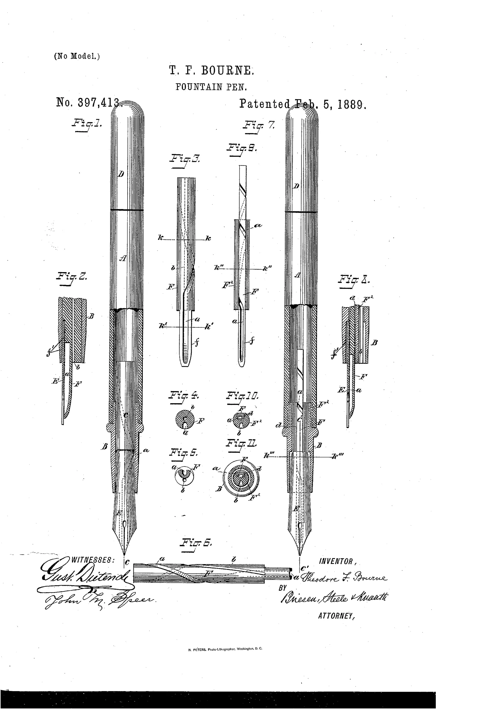
Fountain pen with spiral-groove ink feeder
✒ How it works
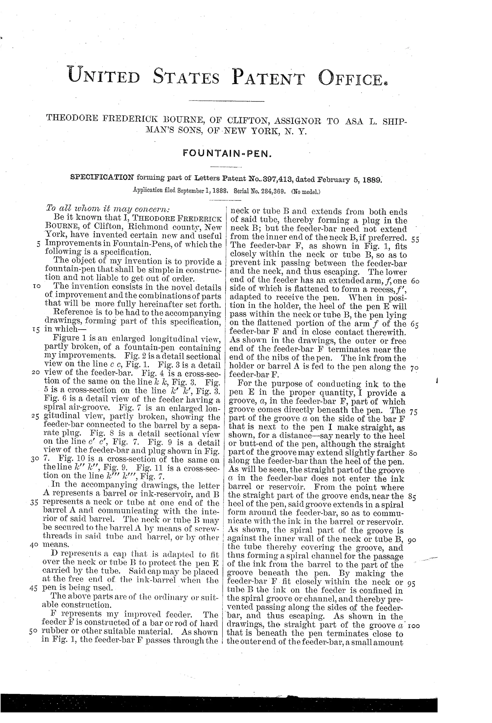
A hard-rubber feeder-bar fits closely within the neck or tube connecting the barrel to the pen. The feeder-bar has a groove that runs straight beneath the pen for a short distance, then spirals around the bar toward the ink in the barrel. This spiral channel is covered by the close-fitting neck or plug, forcing ink to travel along the groove by capillary attraction and gravity to reach the nib. A separate longitudinal air-duct or spiral groove on the feeder allows air to enter the barrel as ink is withdrawn, maintaining equilibrium and preventing excess ink flow.
✒ What was claimed
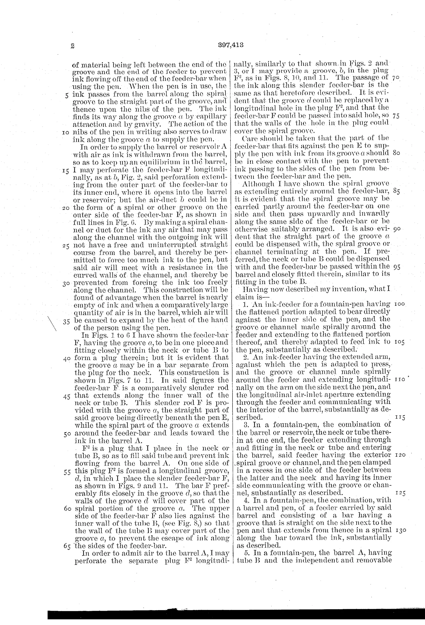
“1. An ink-feeder for a fountain-pen having the flattened portion adapted to bear directly against the inner side of the pen, and the groove or channel made spirally around the feeder and extending to the flattened portion thereof, and thereby adapted to feed ink to the pen, substantially as described.”
In plain English: The invention is an ink feeder with a flattened side that presses against the pen and a spiral groove that carries ink to that flattened area to supply the nib.
✒ In the inventor’s words
“By making a spiral channel or duct for the ink any air that may pass along the channel with the outgoing ink will not have a free and uninterrupted straight course from the barrel, and thereby be permitted to force too much ink to the pen, but said air will meet with a resistance in the curved walls of the channel, and thereby be prevented from forcing the ink too freely along the channel.”— Theodore Frederick Bourne, from the specification
Fate unknown
Assignment to Shipman's Sons, an active pen seller, suggests production intent, but I can't confirm a surviving pen with this spiral feed; a marked Shipman/Bourne specimen with the patent date would settle it.
✒ Commentary
Bourne is attacking the same demon Waterman had just tamed: the surge. In 1888 the failure mode everyone feared was the pen that wrote fine for a page and then dumped a blot when a bubble of air barged up the feed and shoved ink out ahead of it. Waterman's answer was fine capillary fissures. Bourne's answer, here, is geometry — make the ink walk a spiral. His feeder-bar runs straight under the nib for a short stretch, then the groove corkscrews around the bar back toward the barrel, with the close-fitting neck acting as the roof of the channel. His own words give the game away: air escaping down the channel 'will meet with a resistance in the curved walls' and so can't fire ink at the nib.
Figs. 3 through 6 are the ones to study — the small cross-sections show the groove migrating around the bar's circumference, and Fig. 6 shows a second spiral cut for the air return. That two-channel thinking (ink out, air in, kept separate) is exactly right, and it's the part of the patent that ages well.
The spiral itself is a dead end, though. Extra path length means extra drag on the ink as well as the air, and the trade eventually settled on short, straight feeds with fissures doing the throttling. Note the assignee: Asa L. Shipman's Sons, a New York stationery house — this was drawn with a product in mind, not as a lone tinkerer's flyer.
Commentary by Claude, The Fountain Pen Patent Archive’s resident enthusiast