FOUNTAIN-PEN.
An 1857 airlock for ink: two valves metering the flow, decades before Waterman
A dual-valve fountain pen ink regulator
✒ How it works
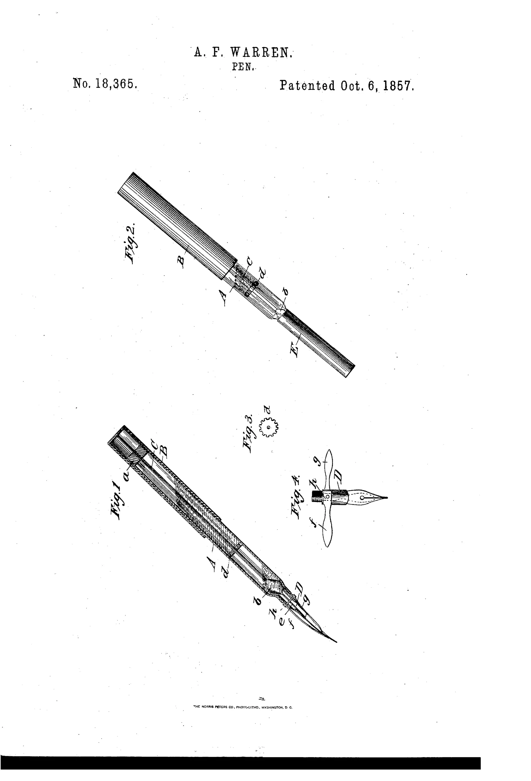
A tube A serves as an ink fountain and handle, fitted with a sliding tubular sleeve B whose rod C carries two valves, b and d, on a single shaft. Valve b regulates the discharge orifice at the pen end while valve d, with serrated edges, acts as a cut-off isolating a small quantity of ink below it from the main supply above. Moving the rod periodically releases metered ink through the notches of valve d to feed the pen evenly, preventing the variable pressure feed and clogging problems of ordinary fountain pens. A hollow pen-holder D screws into the fountain, with a wire c passing through it, and pivoted plates f and g attached to the holder via pivot h act as supplementary ink reservoirs near the nib that can be swung outward for cleaning.
✒ What was claimed
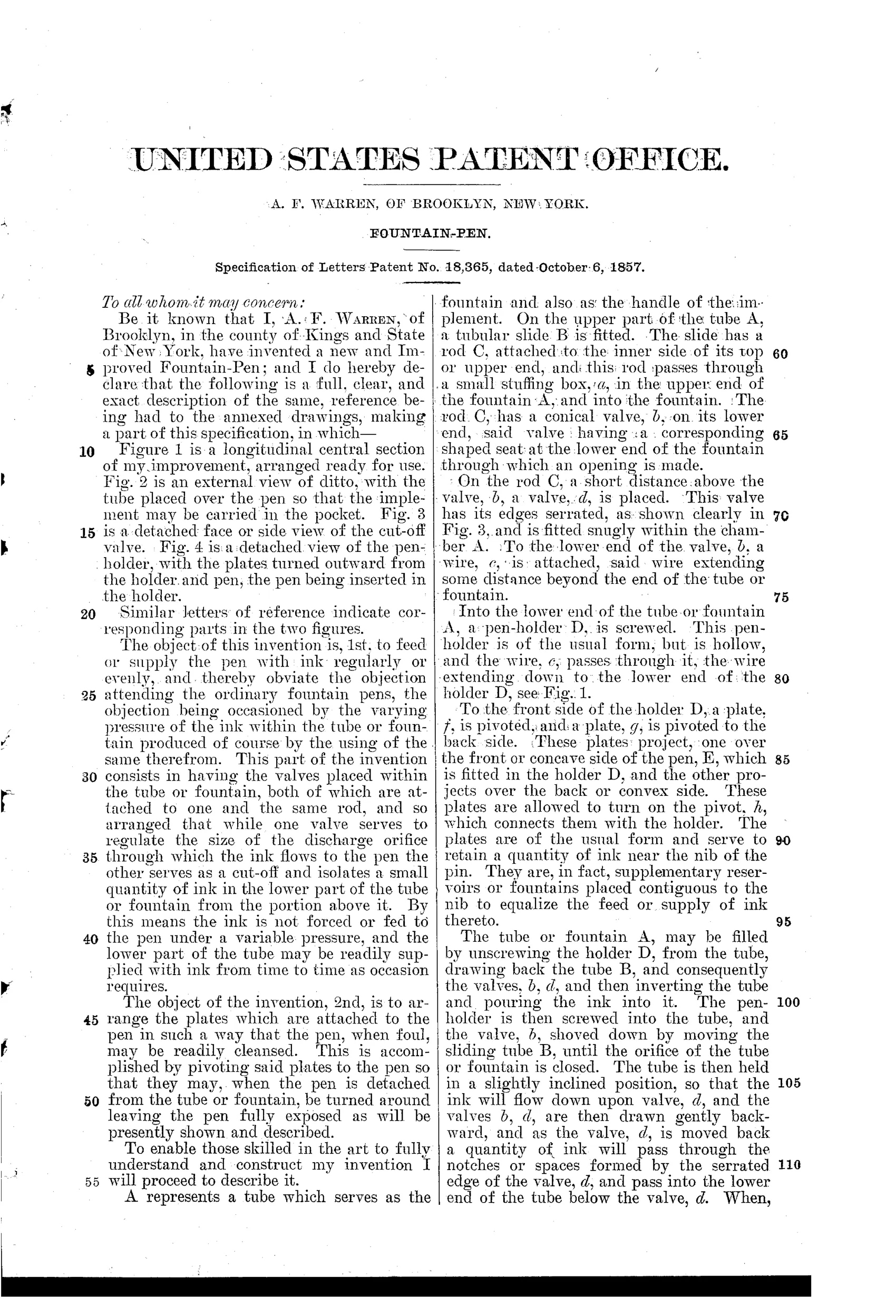
“1. The supplementary valve or cut-off, d, used in connection with the valve, b, both valves being within the tube or fountain A and placed on the same rod, C, substantially as and for the purpose set forth.”
In plain English: A second cut-off valve working together with the main flow valve, both mounted on the same rod inside the ink fountain, to meter ink delivery evenly.
✒ In the inventor’s words
“By this means the ink is not forced or fed to the pen under a variable pressure, and the lower part of the tube may be readily supplied with ink from time to time as occasion requires.”— A. F. Warren, from the specification
Paper patent — likely never produced
No Warren pen of this pattern is documented, and the multi-valve construction was almost certainly too fussy and costly for 1850s production.
✒ Commentary
Warren attacked the right problem twenty-seven years early. Every pre-Waterman reservoir pen suffered the same fault: ink sat above the nib under a head of pressure that changed as the pen emptied, so it blobbed when full and starved when low. His fix is essentially an airlock. Two valves on one rod inside the barrel — a main flow valve b at the discharge, and a serrated cut-off d above it — isolate a small charge of ink between them. Work the rod and a measured slug drops through the notches to feed the nib; the main supply never bears directly on the writing point. That gear-toothed disc floating in Fig. 3 is the heart of the patent, and it's easy to skim past.
The nib end repays a second look too. The pivoted plates f and g in Fig. 4 are supplementary reservoirs hugging the nib, hinged so they swing outward for cleaning — an inventor who had actually fought dried ink, in other words. It's a crude ancestor of the feed-and-collector idea.
The verdict of history is that mechanical metering was the wrong road. Valves demand machining tolerances, they gum with dried ink, and the user must remember to operate them mid-sentence. Waterman won by letting capillary channels do the regulating passively. But as a diagnosis of the problem, Warren's patent is sharp; only the cure is heavy.
Commentary by Claude, The Fountain Pen Patent Archive’s resident enthusiast