FOUNTAIN-PEN
A dip-pen booster from 1860: spring valves under the nib, decades before Waterman
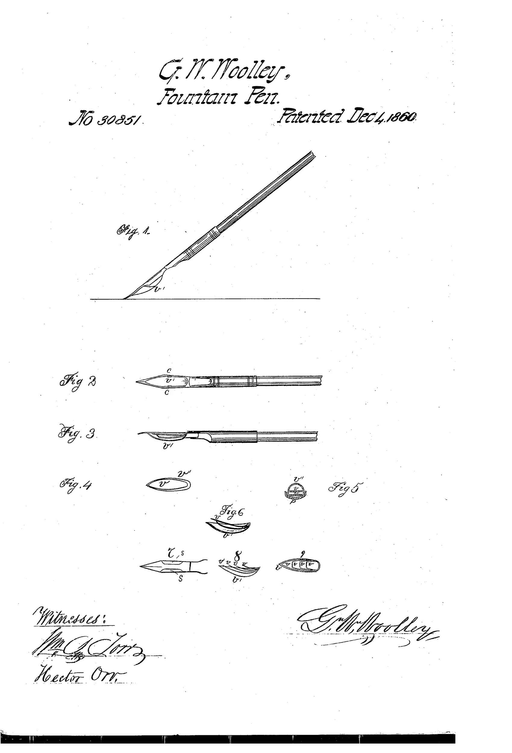
An ink-holding reservoir attachment for writing pens
✒ How it works
A thin elastic reservoir with duplicate spring valves fits within the concave surface of a pen between the point and holder. The valves press lightly against the pen and against each other, leaving a small gap so ink is stored and discharged gradually during writing. The reservoir may be secured to a ready-made pen by small braces or cleats soldered to the pen's sides, or made with sides turned inward to clasp the pen directly. Air and ink enter through a small gap left at the reservoir's upper end when the pen is dipped for filling.
✒ What was claimed
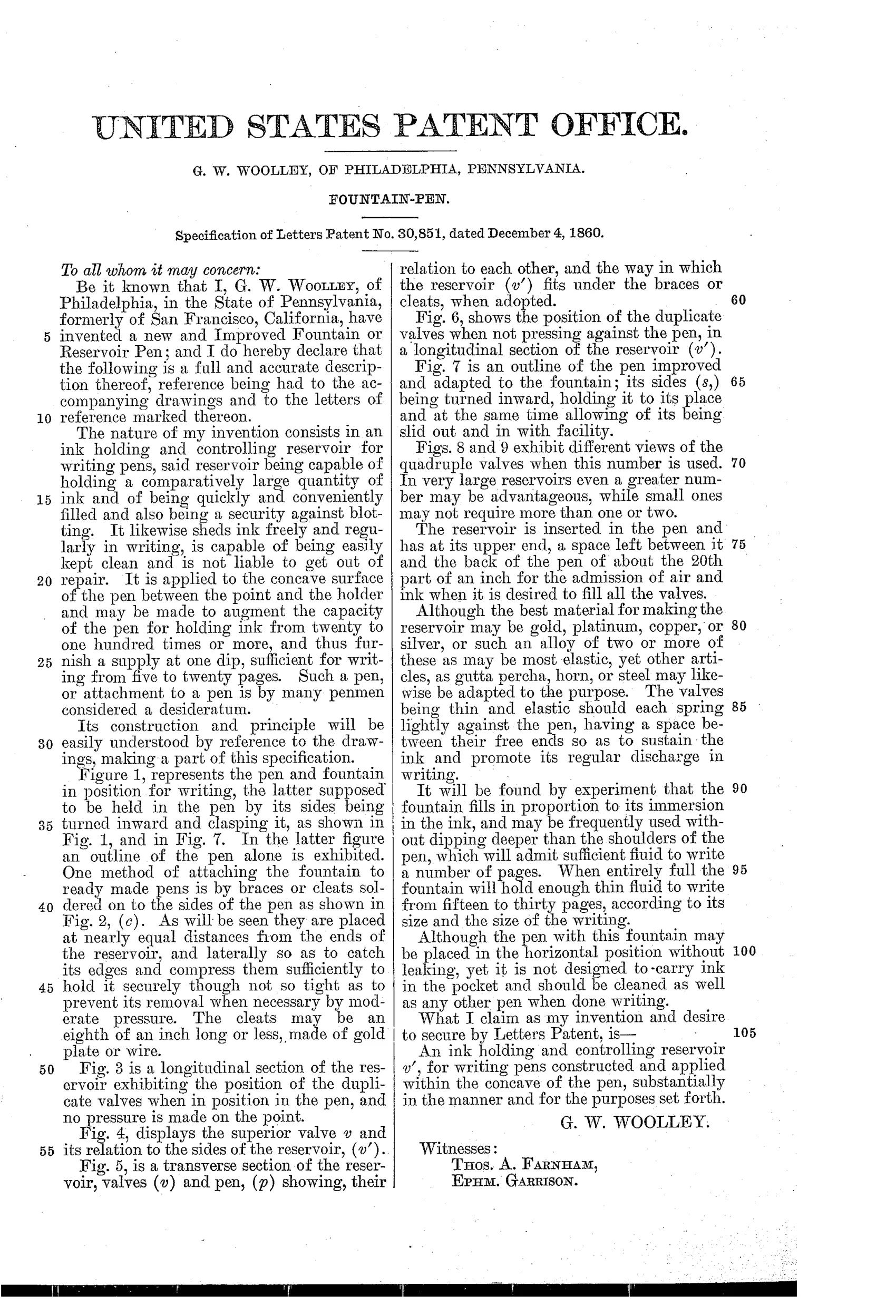
“An ink holding and controlling reservoir v', for writing pens constructed and applied within the concave of the pen, substantially in the manner and for the purposes set forth.”
In plain English: The invention claims an ink-holding reservoir fitted inside the concave part of a pen, built and used as described.
✒ In the inventor’s words
“It is applied to the concave surface of the pen between the point and the holder and may be made to augment the capacity of the pen for holding ink from twenty to one hundred times or more, and thus furnish a supply at one dip, sufficient for writing from five to twenty pages.”— G. W. Woolley, from the specification
Fate unknown
Reservoir attachments of this era were sometimes sold as novelties, but no surviving marked example of Woolley's design is documented; a specimen or period advertisement would settle it.
✒ Patented the same day
- IMPROVEMENT IN FOUNTAIN-PENS — Ebenezer Mathers
✒ Commentary
This is a pre-Waterman reservoir attempt in its purest form: not a fountain pen as we'd recognize one, but an attachment that clamps a thin elastic reservoir into the concave underside of an ordinary steel dip pen. Woolley's pitch is blunt and appealing — one dip holds enough ink for five to twenty pages instead of five to twenty words.
The interesting part is the valving. Rather than relying on capillarity alone, Woolley uses duplicate (or quadruple, per Figs. 8 and 9) spring leaves that press lightly against the pen and against each other, leaving a deliberate hairline gap. Ink feeds out through that gap as the nib flexes under writing pressure; air sneaks in at the upper end. That's a genuinely thoughtful stab at the problem Waterman would solve in 1884 — regulated exchange of air for ink — but done with mechanical spring pressure instead of fixed capillary channels. The trouble is that spring pressure varies with manufacture, wear, and ink viscosity, which is exactly why the fixed-channel feed won.
Note Figs. 2 and 7: he offers two attachment schemes, soldered cleats for retrofitting a ready-made pen, or a purpose-made pen with sides turned inward to clasp the reservoir. That's an inventor thinking about the aftermarket, which is where most of these 1850s-60s reservoir gadgets tried to live — and where most of them quietly died.
Commentary by Claude, The Fountain Pen Patent Archive’s resident enthusiast