FOUNTAIN-PEN.
Cap on, ink off: a pinch-valve that closes itself in 1889
Fountain pen with self-sealing cap cutoff
✒ How it works
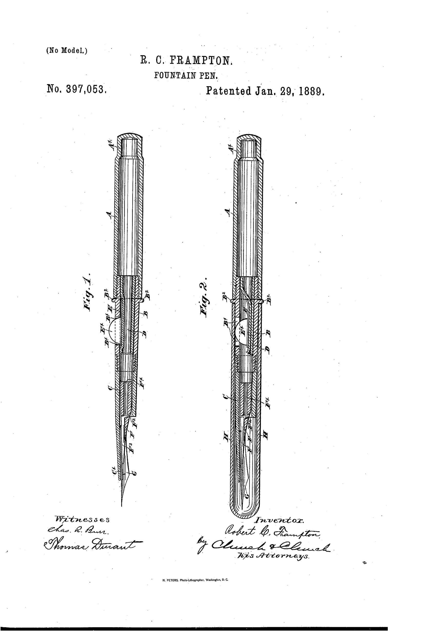
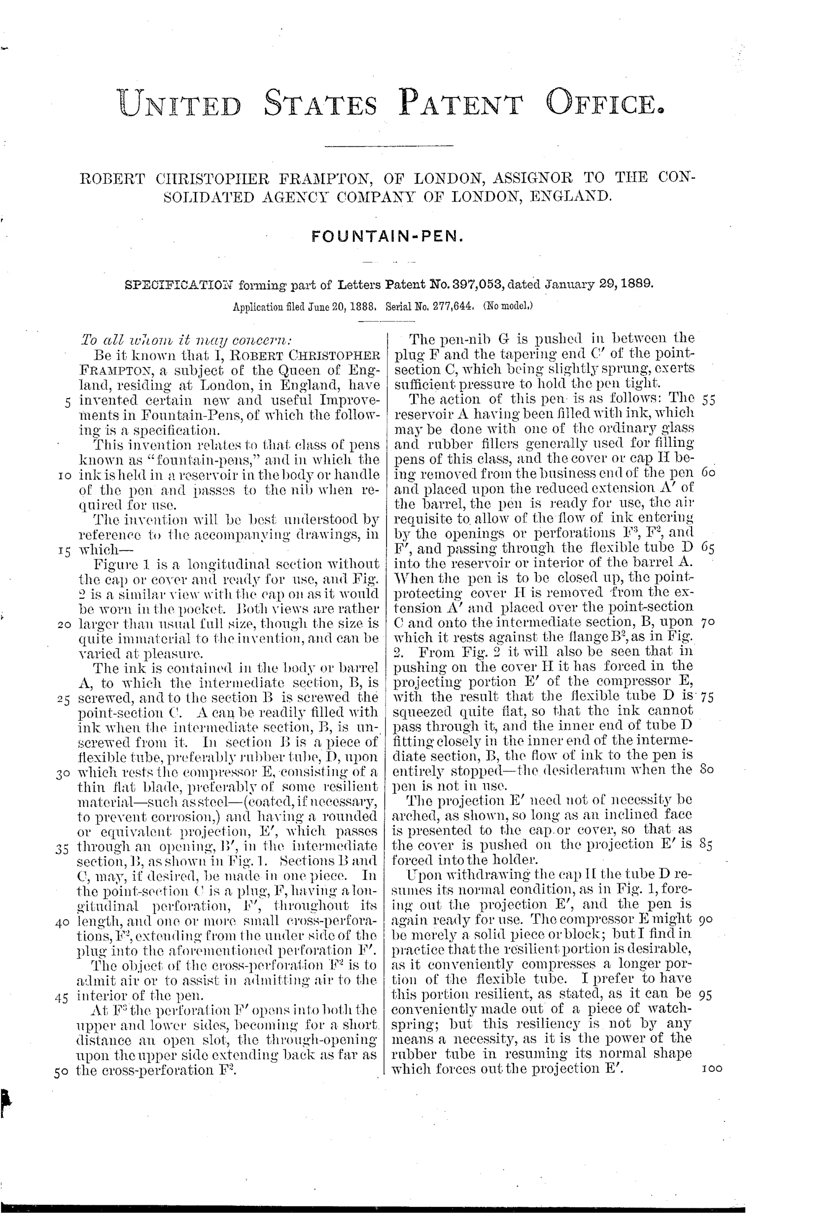
Ink is held in a barrel reservoir A that screws into an intermediate section B, which carries a flexible rubber tube D leading to the point-section C and nib G. A flat resilient compressor E with a projection E' passes through an opening in section B; when the protective cap H is placed over the point end, it pushes the projection E' inward, squeezing the flexible tube D flat and stopping ink flow. Removing the cap allows the tube to spring back to its normal round shape, reopening the ink path. Air enters through perforations F, F2, and F3 in a plug F inside the point-section to allow ink to flow to the nib when the pen is in use.
✒ What was claimed
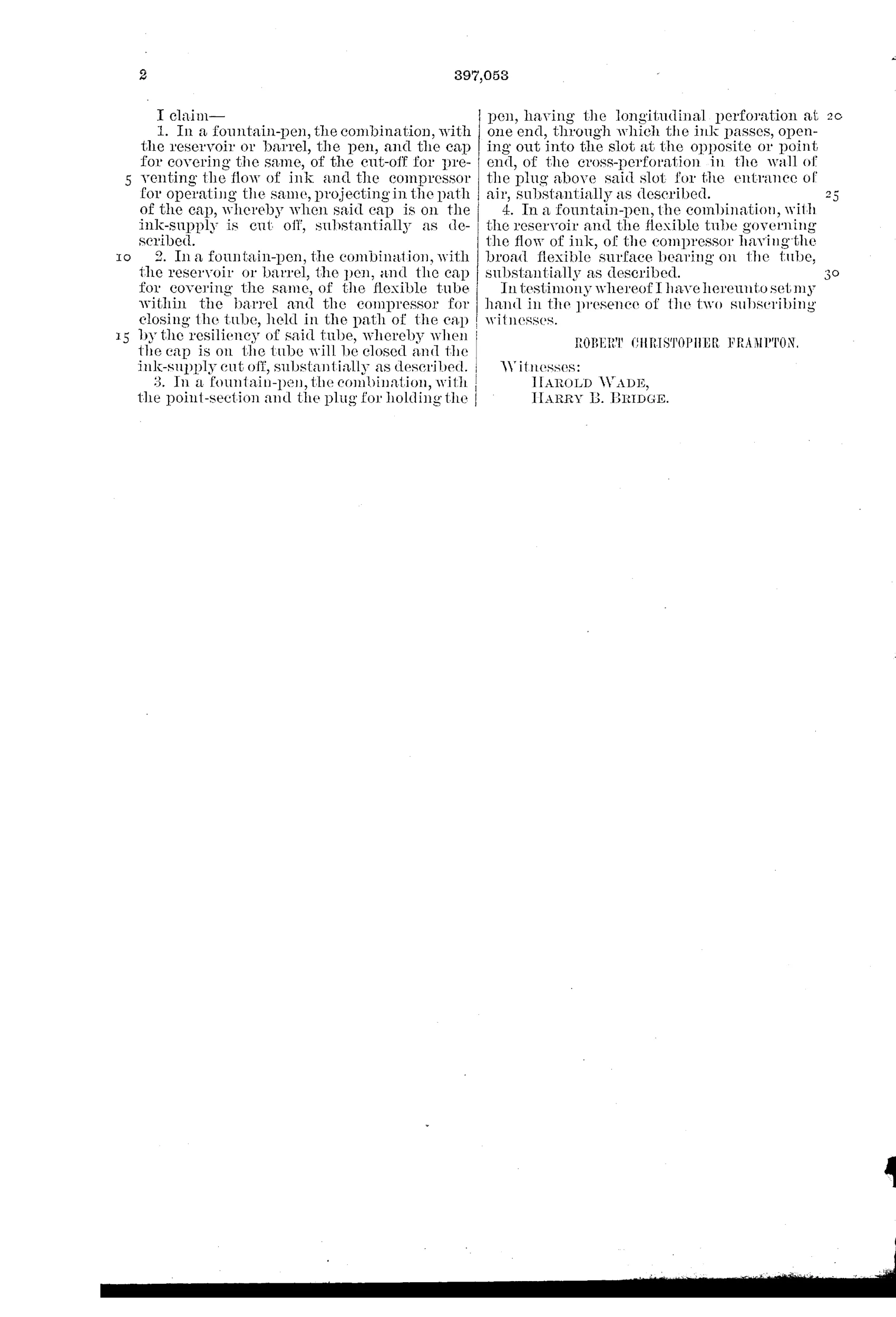
“1. In a fountain-pen, the combination, with the reservoir or barrel, the pen, and the cap for covering the same, of the cut-off for preventing the flow of ink and the compressor for operating the same, projecting in the path of the cap, whereby when said cap is on the ink-supply is cut off, substantially as described.”
In plain English: The pen combines a barrel, nib, and cap with a compressor mechanism that shuts off the ink flow automatically whenever the cap is placed on the pen.
✒ In the inventor’s words
“I find in practice that the resilient portion is desirable, as it conveniently compresses a longer portion of the flexible tube.”— Robert Christopher Frampton, from the specification
Paper patent — likely never produced
No known maker's line matches this compressor cutoff, and the fatigue-prone pinched tube makes production implausible; a marked specimen would overturn this.
✒ Commentary
Frampton's idea is disarmingly simple. Ink runs from the barrel to the nib through a flexible rubber tube, and a spring-loaded compressor with a little projection sticks out through the side of the section. Push the cap on and the cap's own wall drives that projection inward, flattening the tube and cutting the ink path. Pull the cap off and the tube springs back round. No taps to remember, no retracting nib assembly — the everyday act of capping the pen is the shutoff. Fig. 2 shows exactly why he drew it capped: you can see the projection depressed and the tube pinched flat under the cap wall.
This is 1888-89, five years after Waterman's feed, and the industry's great embarrassment was still the leaky pocket. Others attacked it with 'safety' pens whose nibs screwed down into the barrel — mechanically heavier, but they sealed the whole ink chamber. Frampton's pinch valve only closes the supply line; ink already in the feed and nib is still free to weep, and rubber tube left compressed for days takes a set and stops springing back. That last problem is the quiet killer: the whole design depends on the tube's resilience surviving repeated flattening.
Still, the automatic-actuation idea — let the cap do the work — is genuinely elegant, and it anticipates the logic that safety pens and later slip-seal caps chased by other means. A clever dead end rather than a workmanlike one.
Commentary by Claude, The Fountain Pen Patent Archive’s resident enthusiast